
Electrode array of touch panel

a touch panel and electrode array technology, applied in the field of touch panel, can solve the problems of touch panel damage, touch panel may be struck and burned at various times, product reliability and sensing accuracy are reduced,

Inactive Publication Date: 2013-11-28
CHUNGHWA PICTURE TUBES LTD
View PDF3 Cites 20 Cited by
  • Summary
  • Abstract
  • Description
  • Claims
  • Application Information

AI Technical Summary

Benefits of technology

The present invention provides an electrode array for a touch panel using dumbbell-shaped electrodes. This design solves the problem of bridge wires easily breaking, which improves product reliability and accuracy of touch positions.

Problems solved by technology

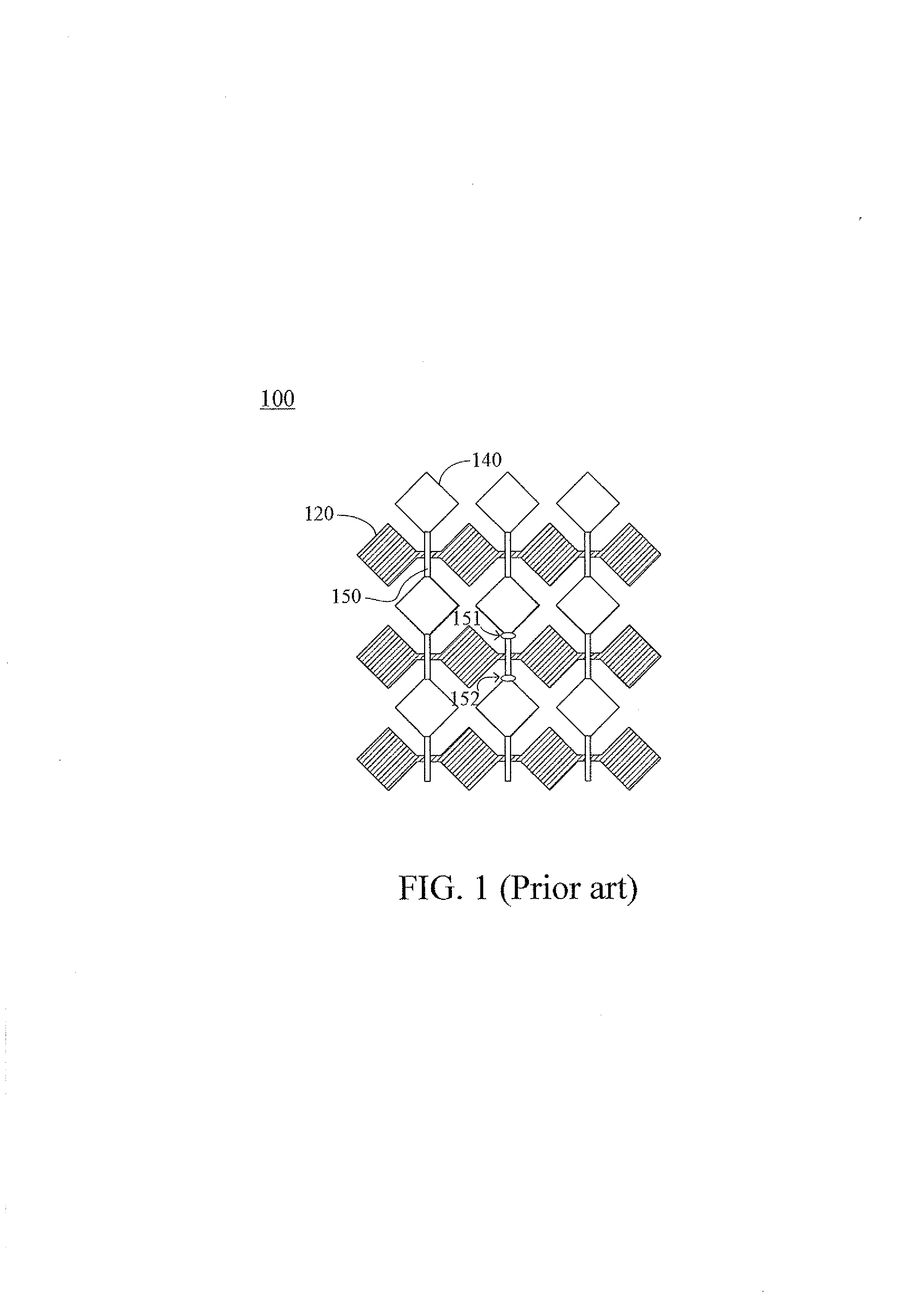
When a user operates a product with a capacitive touch panel, a function of the touch panel is damaged because of the existence of ESD.
In a releasing process, the touch panel may be struck and burnt at various situations and places where charges can easily accumulate such as thin, tip, and bending places.
An entire column of the rhombus-shaped electrodes where the burnt-out place is located fails to work; thus product reliability and sensing accuracy are reduced.

Method used


Image

  • Electrode array of touch panel
  • Electrode array of touch panel
  • Electrode array of touch panel

Examples


Embodiment Construction

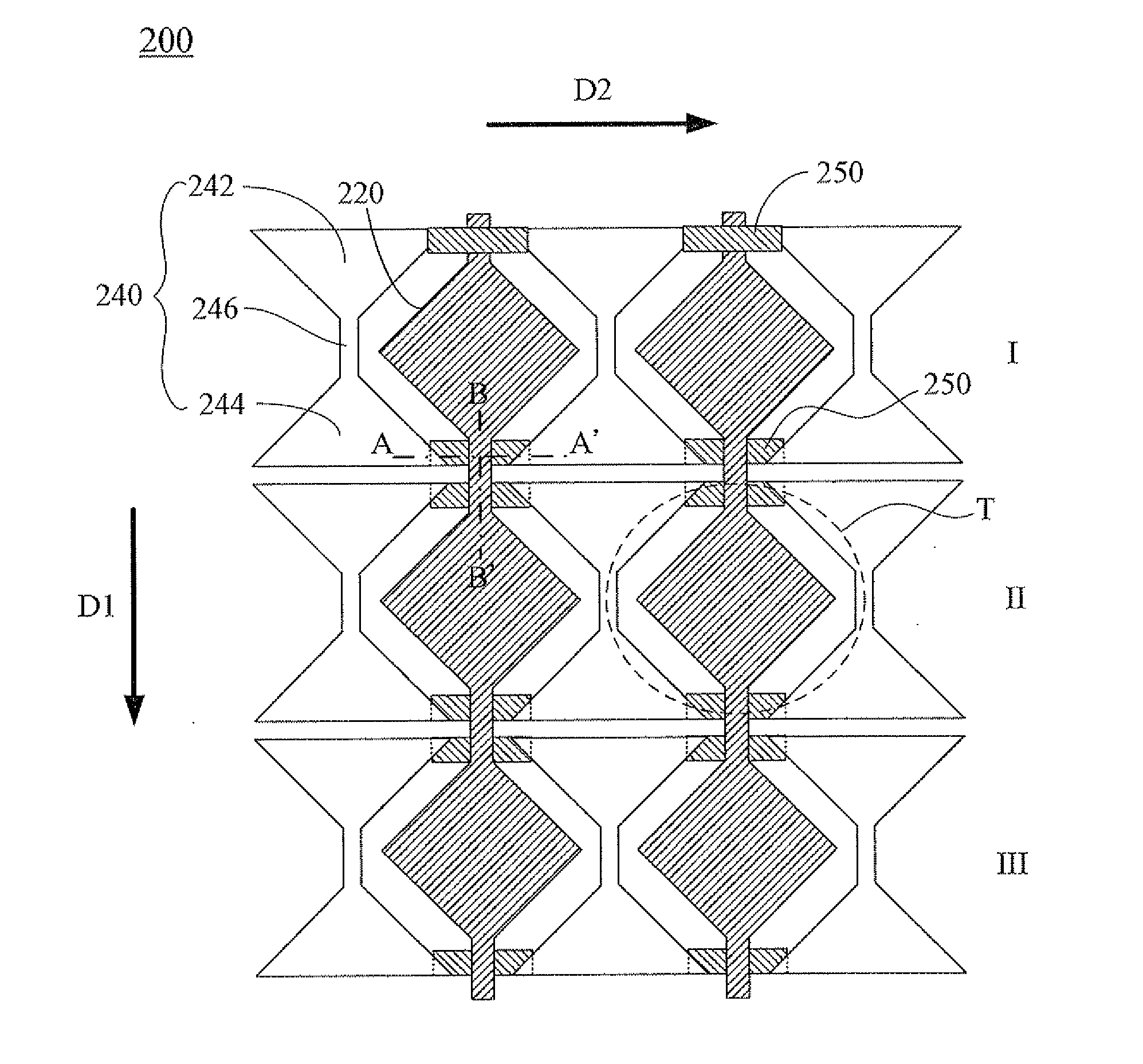
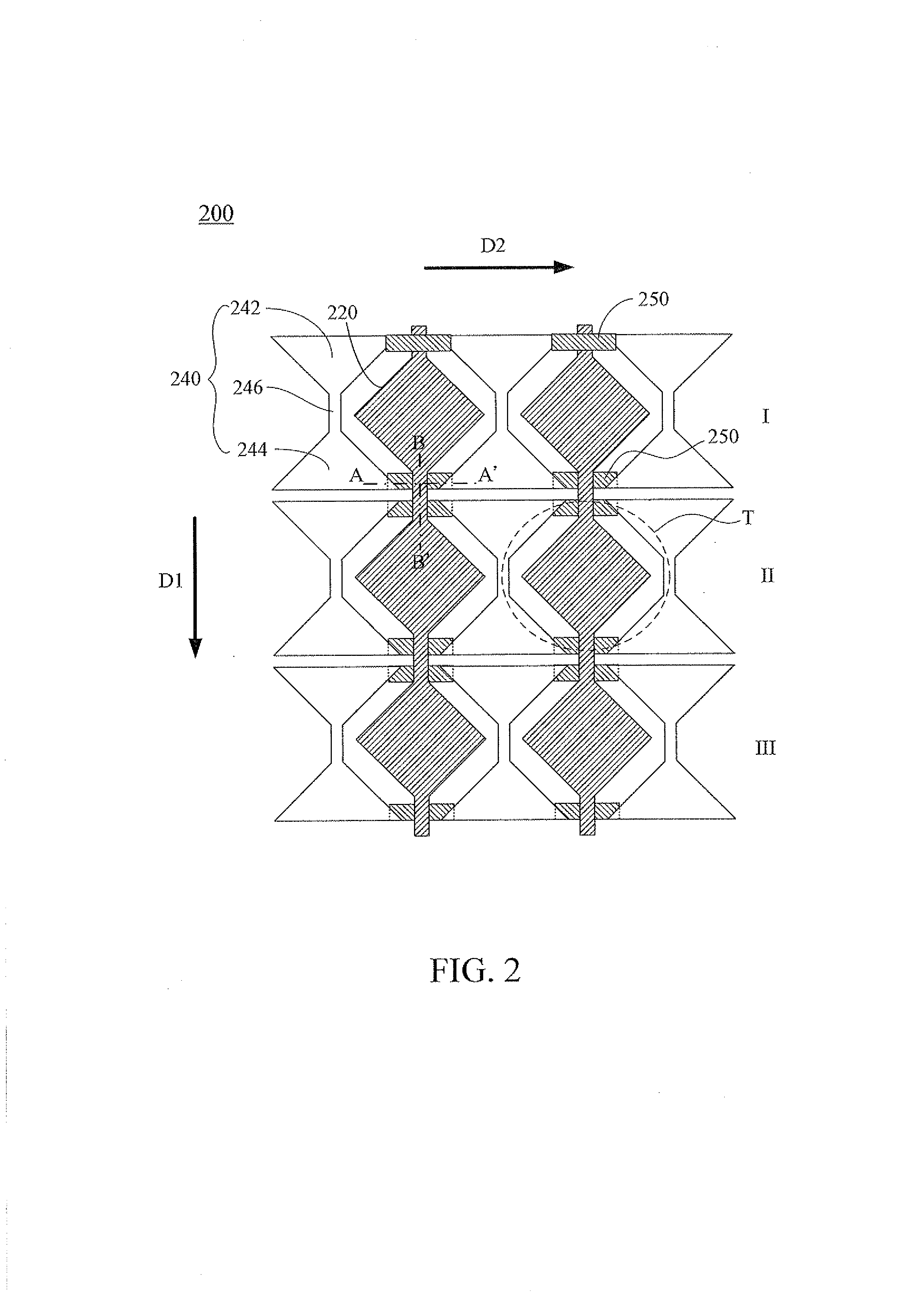
[0020]The present invention will now be described in detail with reference to a preferred embodiment, thereof as illustrated in the accompanying drawings In different drawings the same reference numbers will be used throughout the drawings to refer to the same or like parts. Referring to FIG. 2, FIG. 2 is a top view schematically illustrating an electrode array of a touch panel according to a first preferred embodiment of the present invention, in which the electrode array according to the preferred embodiment is generally designated at 200. The electrode array 200 includes a plurality of rhombus-shaped electrodes 220, a plurality of dumbbell-shaped electrodes 240, and a plurality of bridge wires 250.

[0021]As shown in FIG. 2, the rhombus-shaped electrodes 220 are arranged along a first direction D1 into a plurality of columns, and the rhombus-shaped electrode 220 of each column is interconnected in the first direction D1. In the preferred embodiment, the first direction D1 is a vert...


PUM


Abstract

Disclosure is an electrode array of a touch panel, which includes a plurality of rhombus-shaped electrodes, dumbbell-shaped electrodes, and bridge wires. The rhombus-shaped electrodes are arranged along a first direction and interconnected in the first direction. The dumbbell-shaped electrodes are arranged along a second direction. Each dumbbell-shaped electrode has a first enlarged part, a second enlarged part, and a narrow part. Here, each rhombus-shaped electrode is disposed between two adjacent dumbbell-shaped electrodes along the second direction. The bridge wires are used for electrically coupling the two first enlarged parts and the two second enlarged parts of the two adjacent dumbbell-shaped electrodes, respectively. The production reliability of the present invention is increased according to the dumbbell-shaped electrodes.

Description

TECHNICAL FIELD OF THE INVENTION[0001]The present invention relates to a touch panel, and especially to an electrode array of a touch panel.BACKGROUND OF THE INVENTION[0002]In recent years, applications of consumer electronics having capacitive touch panels are already a mainstream market design. Enhancement of sensing characteristic is one of important development goals at the current stage. Currently, there is an urgent need to improve an electrostatic discharge (ESD) problem. When a user operates a product with a capacitive touch panel, a function of the touch panel is damaged because of the existence of ESD. This problem has become the focus and concern for improvement for the manufacturers.[0003]Electrostatic charges are usually generated by rubbing or other reasons while using the capacitive touch panel or manufacture processes thereof. Greater electrostatic charges can easily lead to the ESD effect to release electrical energy. In a releasing process, the touch panel may be s...

Claims


Application Information

Patent Timeline
Patent Type & Authority Applications(United States)
IPC IPC(8): H03K17/975
CPCG06F2203/04111G06F3/0443G06F3/0446H03K17/9622H03K2017/9602
Inventor CHANG, CHIH-CHAOHSU, CHAO-YONGHUANG, SHIH-HUNGCHEN, HUNG-HSIANG
Owner CHUNGHWA PICTURE TUBES LTD
Learn More