Positioning structure for removable hard drive

a technology of fixing structure and removable hard drive, which is applied in the direction of rotating cabinets, instruments, casings with display/control units, etc., can solve the problems of complication and inconvenience, difficult positioning and asymmetry of fastening force, etc., and achieve the effect of convenient installation and positioning

Active Publication Date: 2013-11-28
AIC INC
View PDF15 Cites 10 Cited by
  • Summary
  • Abstract
  • Description
  • Claims
  • Application Information

AI Technical Summary

Benefits of technology

[0008]An object of the invention is to provide a positioning structure for a removable hard drive which has an advantage of easy installation and positioning.
[0009]Another object of the invention is to provide a positioning structure for a removable hard drive which does not require any hand tool when installing and positioning and can avoid loss of screws.

Problems solved by technology

However, current removable hard drive racks usually require a hand tool to fasten screws into a case.
Because the screws are symmetrically fastened to two opposite sides of the removable hard drive rack, difficulty of positioning and asymmetry of fastening forces happens frequently.
Moreover, the disassembled screws are hard to be kept and a hand tool is required when installing and disassembling, these will cause complication and inconvenience.

Method used


Image

  • Positioning structure for removable hard drive
  • Positioning structure for removable hard drive
  • Positioning structure for removable hard drive

Examples


Embodiment Construction

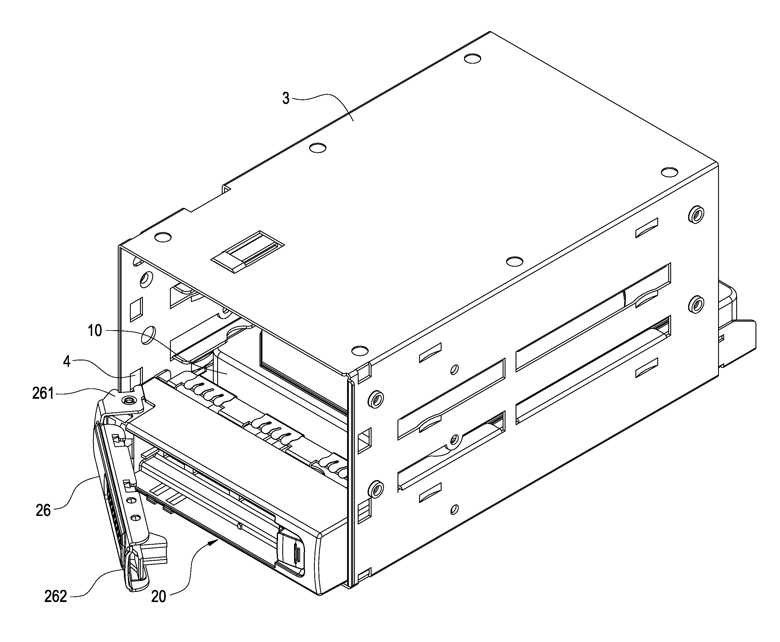
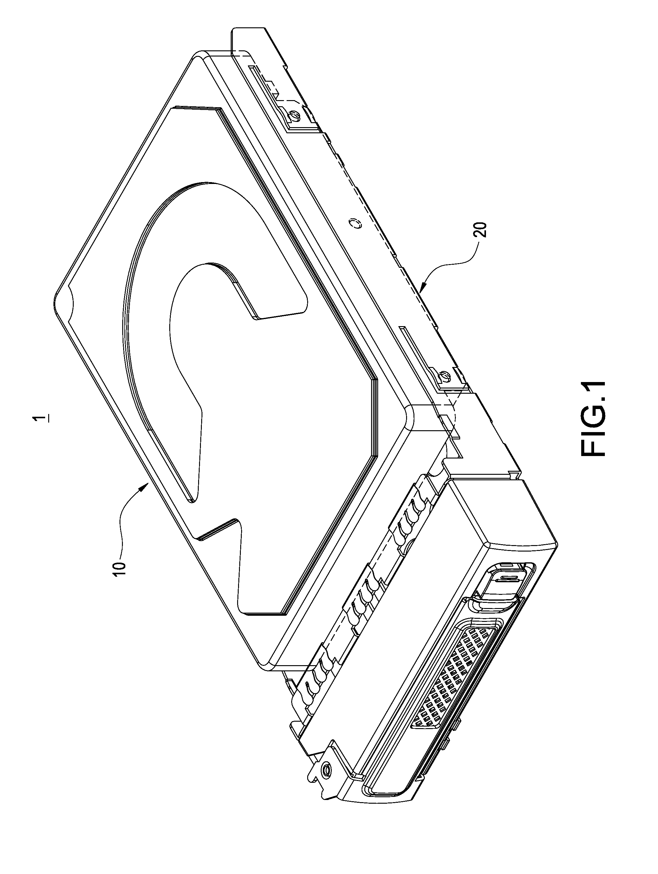
[0017]Please refer to FIG. 1. The positioning structure 1 for a removable hard drive of the invention includes an enclosure 10 and a tray 20. The enclosure 10 is received in the tray 20.

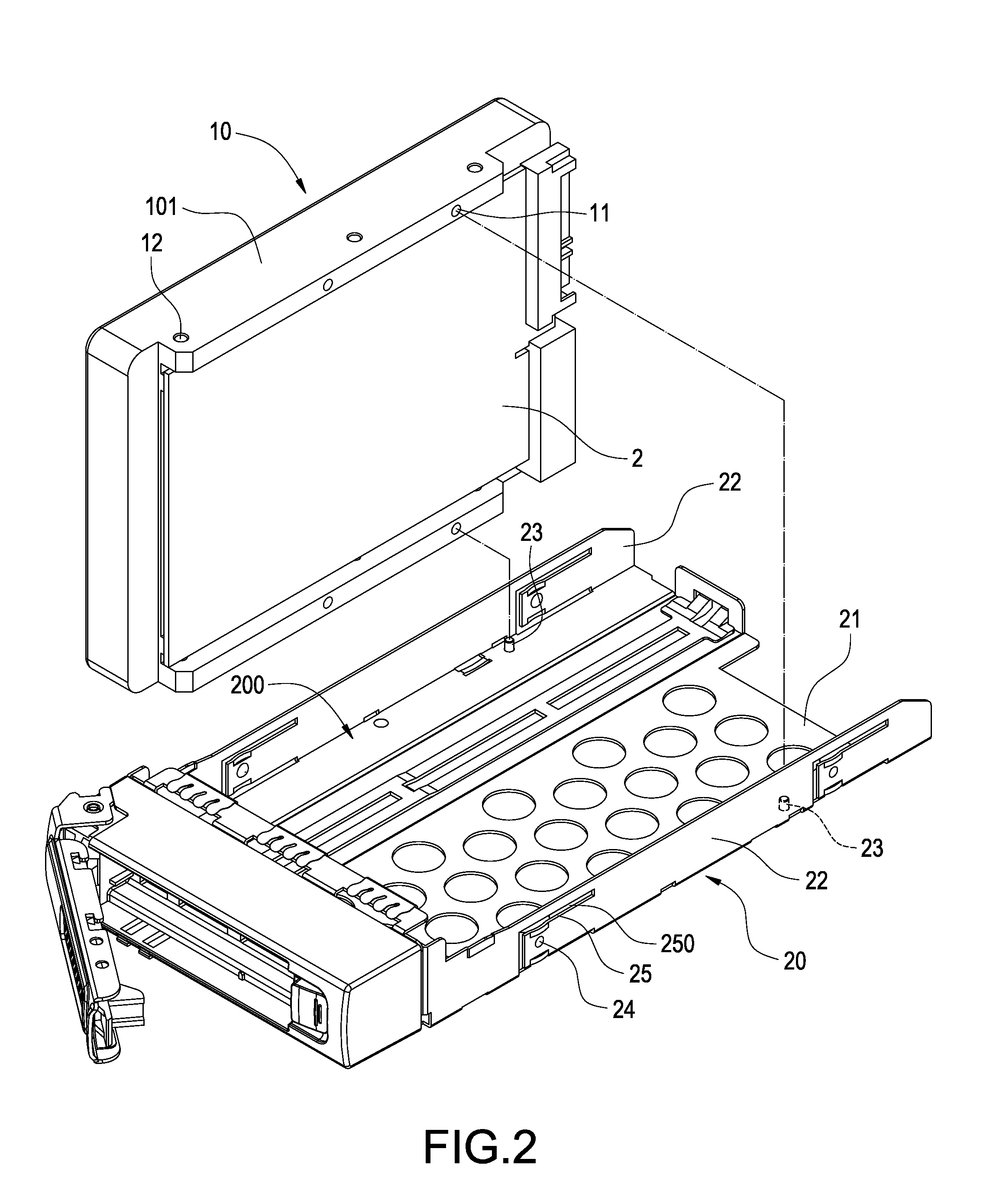
[0018]Please refer to FIG. 2. A hard drive 2 is mounted in the enclosure 10. The bottom of the enclosure 10 is provided with a plurality of positioning holes 11.

[0019]The tray 20 includes a bottom 21 and two side walls 22 vertically extending from the bottom 21. A space 200 is formed by the bottom 21 and the side walls 22. The bottom 21 is formed with a plurality of positioning pillars 23 corresponding to the positioning holes 11. The enclosure 10 is received in the space 200 and the positioning holes 11 are correspondingly engaged with the positioning pillars 23.

[0020]In a preferred embodiment of the invention, a side 101 of the enclosure 10 is formed with at least one positioning cavity 12. One of the side walls 22 is formed with at least one positioning protrusion 24. In the embodiment, each of th...


PUM


Abstract

A positioning structure for a removable hard drive includes an enclosure and a tray. The enclosure is used for being mounted by the hard drive, and disposed with a plurality of positioning holes. The tray includes a bottom and two side walls vertically extending therefrom. A space being is formed by the bottom and the side walls. The bottom is formed with a plurality of positioning pillars corresponding to the positioning holes. The enclosure is received in the space, and the positioning holes are correspondingly inserted by the positioning pillars.

Description

[0001]This application is based on and claims the benefit of Taiwan Application No. 101209737 filed May 23, 2012 the entire disclosure of which is incorporated by reference herein.BACKGROUND OF THE INVENTION[0002]1. Technical Field[0003]The invention relates to a fixture of data storage device, particularly to a fixture of removable hard drive rack.[0004]2. Related Art[0005]With popularization of computers, many kinds of peripheral devices appear in the markets to satisfy user's requirements, for example, a removable hard drive for data storage (installed in a removable hard drive rack). Because of the advantages of plug-and-play and capability for storage of a bulky amount of data, the removable hard drive has been widely adopted by users.[0006]Such a removable hard drive rack can allow a hard drive to be directly detached from a computer case without disassembly. It is more convenient than conventional installation of hard drives.[0007]However, current removable hard drive racks u...

Claims


Application Information

Patent Timeline
Patent Type & Authority Applications(United States)
IPC IPC(8): H05K5/03H05K5/02
CPCG11B33/124H05K5/0008H05K5/0017
Inventor KUO, CHUNG-I
Owner AIC INC
Why Eureka
Try Eureka