Electronic display mount with extreme tilt feature

a technology of electronic display and extreme tilt, which is applied in the direction of machine supports, instruments, manufacturing tools, etc., can solve the problem of only being able to tilt in a limited rang

Inactive Publication Date: 2013-11-28
LEGRAND AV INC
View PDF15 Cites 25 Cited by
  • Summary
  • Abstract
  • Description
  • Claims
  • Application Information

AI Technical Summary

Benefits of technology

[0004]The present invention addresses the need of the industry for an electronic display ...

Problems solved by technology

Such a device has the drawback, however, of being capable of onl...

Method used


Image

  • Electronic display mount with extreme tilt feature
  • Electronic display mount with extreme tilt feature
  • Electronic display mount with extreme tilt feature

Examples


Embodiment Construction

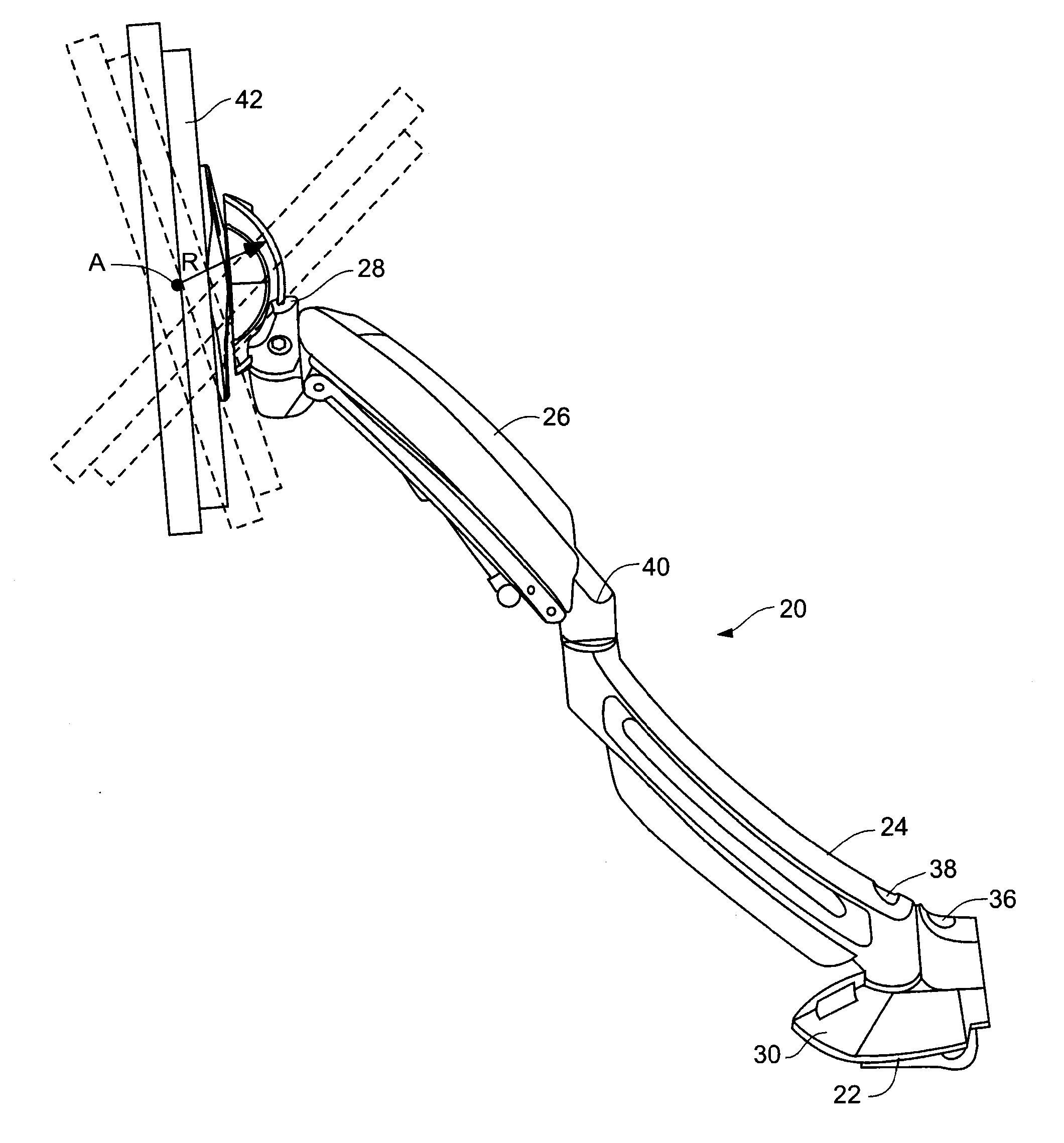
[0024]Mount assembly 20 as depicted in FIGS. 4-9 generally includes desk clamp 22, lower arm 24, upper arm assembly 26, and tilt head assembly 28. Desk clamp 22 generally includes upper desk interface 30 and lower clamp portion 32. Desk interface 30 presents lower surface 34 which, in use, confronts an upwardly facing table or desk surface (not shown). Clamp portion 32 engages the underside of the table or desk surface. Adjustment screw 36 is operable to enable selective positioning of clamp portion 32 such that desk clamp 22 can engage around table or desk surfaces of varying thickness.

[0025]Lower arm 24 is pivotally coupled to desk clamp 22 at pivot 38. Upper arm assembly 26 is pivotally coupled to lower arm 24 at pivot 40 such that upper arm assembly 26 and lower arm 24 combine to form an articulating arm assembly for enabling tilt head assembly 28 and an attached flat panel display device 42 to be selectively positioned laterally side-to-side relative to desk clamp 22. Upper arm...


PUM

PropertyMeasurementUnit
Angleaaaaaaaaaa
Angleaaaaaaaaaa
Angleaaaaaaaaaa

Abstract

A display mount assembly, including a supporting member that engages to an environmental structure at a first end, a display interface coupled to a flat panel display device and a supporting member interface between the supporting member and the display interface. The supporting member interface includes an arcuate guide structure and a follower received therein. The arcuate guide structure subtends a first arcuate length, the ends of which limit arcuate travel of the follower. The follower structure defines a portion of the arcuate channel subtending a second arcuate length such that a difference between the first arcuate length and the second arcuate length is greater than or equal to about fifty degrees.

Description

CLAIM TO PRIORITY[0001]The present application is a National Phase entry of PCT Application No. PCT / US2011 / 062711, filed Nov. 30, 2011, which application claims the benefit of U.S. Provisional Application Ser. No. 61 / 418,377 filed Nov. 30, 2010 and entitled “Electronic Display Mount with Extreme Tilt Feature” the entire contents of which are incorporated herein by reference.FIELD OF THE INVENTION[0002]The present invention relates to electronic display devices such as flat panel electronic displays, and more specifically to mounting devices for flat panel electronic display devices.BACKGROUND OF THE INVENTION[0003]Mounting devices for flat panel electronic display devices are known. For example, U.S. Pat. No. 6,905,101 and U.S. Pat. No. 7,152,836, both owned by the owners of the present invention and hereby incorporated herein by reference, disclose mounting devices for a flat panel electronic displays. Such a device has the drawback, however, of being capable of only a limited rang...

Claims


Application Information

Patent Timeline
IPC IPC(8): G06F1/16H05K13/00
CPCG06F1/1601H05K13/00F16M11/10F16M11/2014F16M11/2092F16M11/24F16M13/022F16M2200/041F16M2200/063Y10T29/49826
Inventor SMITH, PAUL
Owner LEGRAND AV INC
Why Eureka
Try Eureka