Transmission device, reception device, transmission method, and reception method

a technology of transmission device and reception device, which is applied in the direction of wireless communication, transmission path division, wireless commuication services, etc., can solve the problems of limiting the increase in the number of base stations, so as to achieve flexible transmission mode.

Inactive Publication Date: 2013-11-28
PANASONIC INTELLECTUAL PROPERTY CORP OF AMERICA
View PDF22 Cites 42 Cited by
  • Summary
  • Abstract
  • Description
  • Claims
  • Application Information

AI Technical Summary

Benefits of technology

[0022]The present invention can provide a transmitting apparatus, a receiving apparatus, a transmission scheme, and a reception scheme capable of flexibly setting a transmission mode even when both a first resource region usable for both a control channel and a data channel, and a second resource region usable for a control channel are included as candidates of resource regions used to transmit a control signal to one receiving apparatus.

Problems solved by technology

The installation of base stations involves reasonable costs, however.
For this reason, there has been a high demand for a technique that provides a communication service using a high-frequency radio band, while limiting an increase in the number of base stations.
Given the introduction of various apparatuses as radio communication terminals in the future M2M (machine to machine) communication, for example, there is a concern for a shortage of resources in the mapping region for PDCCH (i.e., “PDCCH region”) due to an increase in the number of terminals.
If PDCCH cannot be mapped due to such a resource shortage, the DL data cannot be scheduled for the terminals.
Thus, the resource region for mapping DL data (i.e., “PDSCH (physical downlink shared channel) region”) cannot be used even if there is an available region, possibly causing a decrease in the system throughput.

Method used


Image

  • Transmission device, reception device, transmission method, and reception method
  • Transmission device, reception device, transmission method, and reception method
  • Transmission device, reception device, transmission method, and reception method

Examples


embodiment 1

Overview of Communication System

[0048]A communication system according to Embodiment 1 of the present invention has base station 100 and terminal 200. The communication system is an LTE-A system, for example. Base station 100 is an LTE-A base station, and terminal 200 is an LTE-A terminal, for example.

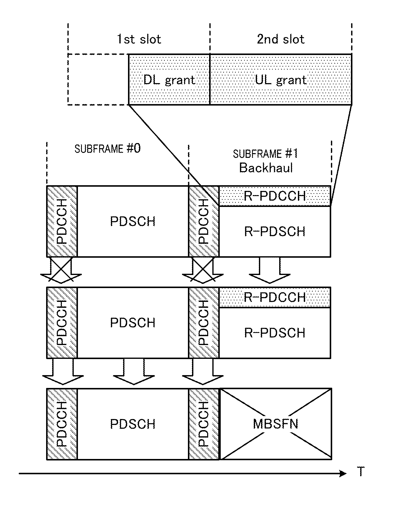
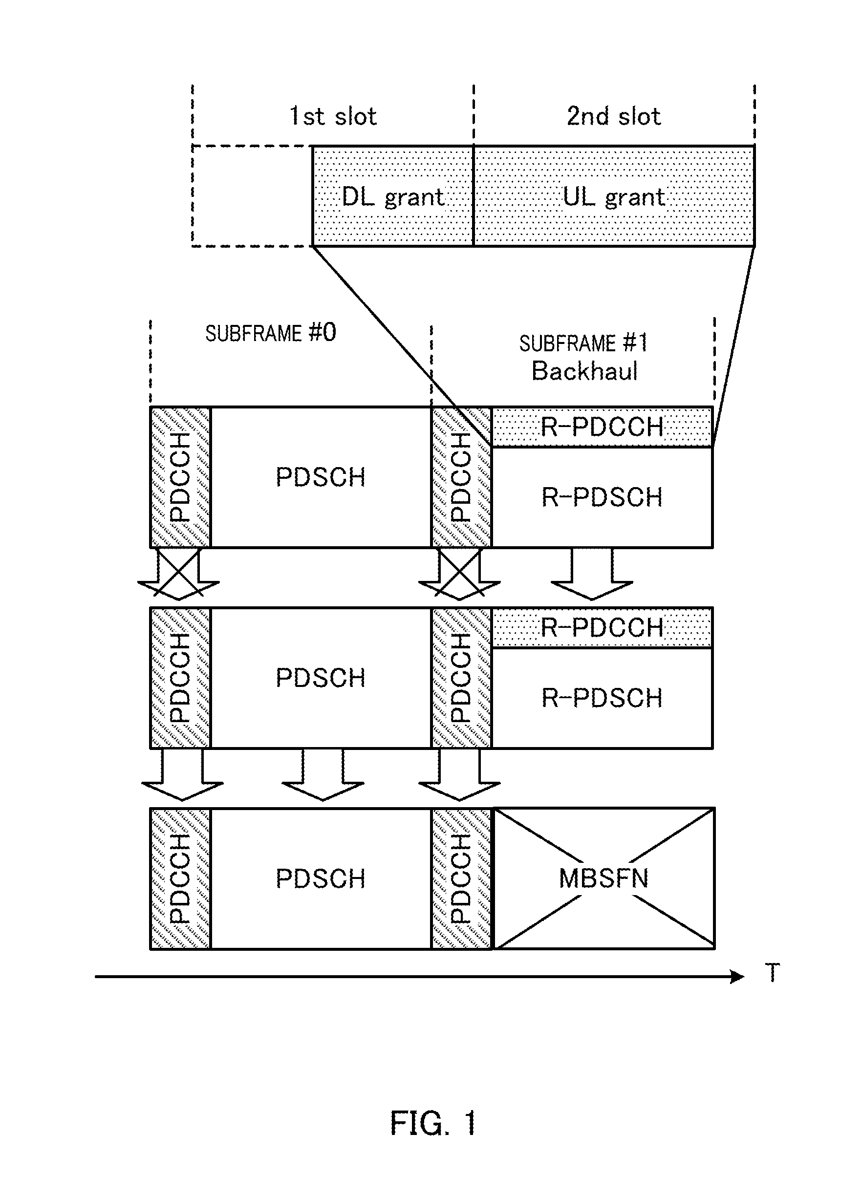
[0049]FIG. 5 illustrates a main configuration of base station 100 according to Embodiment 1 of the present invention. Base station 100 transmits control signals for terminal 200 after mapping the control signals to a first resource region usable for both a control channel and a data channel (i.e., R-PDCCH region in an LTE-A system) or in a second resource region usable for a control channel (i.e., PDCCH region in an LTE-A system). Furthermore, the first resource region and the second resource region are arranged in a subframe in the order of the second resource region and the first resource region in the time direction.

[0050]In base station 100, transmission mode setting section 101 se...

embodiment 2

[0090]As with Embodiment 1, Embodiment 2 sets one transmission mode for each of a first downlink resource region and a second downlink resource region out of a plurality of transmission modes associated with a plurality of control signal formats (that is, DCI formats) and transmission schemes corresponding to the respective control signal formats and used for data transmission to terminal 200. However, in Embodiment 2, the transmission mode set for the second downlink resource region (that is, PDCCH region in an LTE-A system) is fixed. Since a base station and a terminal according to Embodiment 2 are similar to base station 100 and terminal 200 according to Embodiment 1, these will be described using FIGS. 7 and 8.

[0091]In base station 100 of Embodiment 2, transmission mode setting section 101 sets respective transmission modes for PDCCH and R-PDCCH. However, in Embodiment 2, the transmission mode set for the PDCCH region is fixed.

[0092]Here, transmission mode setting section 101 ge...

embodiment 3

[0097]As with Embodiment 1, Embodiment 3 sets one transmission mode for each of a first downlink resource region and a second downlink resource region out of a plurality of transmission modes associated with a plurality of control signal formats (that is, DCI formats) and transmission schemes corresponding to the respective control signal formats and used for data transmission to terminal 200. However, Embodiment 3 generates a control signal including identification information corresponding to a pair of transmission mode information corresponding to PDCCH and transmission mode information corresponding to R-PDCCH, and reports the generated control signal through one kind of signaling. Since a base station and a terminal according to Embodiment 3 are similar to base station 100 and terminal 200 according to Embodiment 1, these will be described using FIGS. 7 and 8.

[0098]In base station 100 of Embodiment 3, transmission mode setting section 101 sets respective transmission modes for ...


PUM


Abstract

A transmission device capable of flexibly setting the transmission mode, even in cases when the candidates for the resource domain to be used to transmit a control signal to a terminal include both a first downlink resource domain that can be used as either a control channel or a data channel and a second downlink resource domain that can be used as a control channel, wherein a transmission mode setting unit (101) sets one transmission mode for each of the first and second downlink resource domains, said transmission mode being selected from among a plurality of transmission modes in which a plurality of control signal formats and the transmission methods that correspond to the control signal formats and are used to transmit data to a terminal (200) have been associated.

Description

TECHNICAL FIELD[0001]The present invention relates to a transmitting apparatus, a receiving apparatus, a transmission method scheme, and a reception method.BACKGROUND ART[0002]In recent years, it has become common to transmit large-volume data, such as still image data and moving image data in addition to audio data in cellular mobile communication systems, in response to spread of multimedia information. Active studies associated with techniques for achieving a high transmission rate in a high-frequency radio band has been conducted to achieve large-volume data transmission.[0003]When a high frequency radio band is utilized, however, attenuation increases as the transmission distance increases, although a higher transmission rate can be expected within a short range. Accordingly, the coverage area of a radio communication base station apparatus (hereinafter, abbreviated as “base station”) decreases when a mobile communication system using a high frequency radio band is actually put...

Claims


Application Information

Patent Timeline
Patent Type & Authority Applications(United States)
IPC IPC(8): H04W72/04
CPCH04W72/0406H04N1/00106H04W72/00H04L5/0053H04L5/0092H04L5/001H04W72/23H04N1/00108H04L5/0051H04W72/20
Inventor HORIUCHI, AYAKOOIZUMI, TORUNISHIO, AKIHIKO
Owner PANASONIC INTELLECTUAL PROPERTY CORP OF AMERICA
Why Eureka
Try Eureka