Process for setting the pivotal angle of the curve headlights of a vehicle

a technology for curve headlights and headlight heads, which is applied in the direction of vehicle position/course/altitude control, process and machine control, instruments, etc., can solve the problems of inconsistent illumination of the area in front of the vehicle, relatively abrupt changes in the area that are illuminated, and the likelihood of the driver following the proposed route is very high, so as to accelerate the determination and reduce the error range. , the effect of accelerating the determination

Inactive Publication Date: 2013-11-28
HELLA KG HUECK & CO
View PDF3 Cites 4 Cited by
  • Summary
  • Abstract
  • Description
  • Claims
  • Application Information

AI Technical Summary

Benefits of technology

[0013]Reducing the projection distance when approaching a crossroad or intersection is referred to as the predictive curve light of a vehicle. The process based on this concept selectively develops this so-called predictive curve light, thereby preventing the undesirable flickering of the lights, i.e. the standard light function only switches to predictive curve light when there is a high probability that the vehicle will actually turn at the crossroad or intersection. The predictive curve light is suppressed in all other cases, thereby ensuring that the driver has a well-illuminated view of the expected route along the main road even when crossroads or intersections are approached. Moreover, unnecessary actuation or unnecessary switching operations in the inner mechanisms of the curve headlights are thereby prevented, reducing wear and increasing the life cycle of the headlights.
[0016]It can be advantageous to use the vehicle speed as the single criterion for determining the expected vehicle route when using the process defined based on this concept. The slower the speed of the vehicle when approaching a crossroad or intersection the higher the probability that the vehicle will turn. The criterion should preferably be a threshold value for the vehicle speed. If the vehicle slows to a speed below that threshold, it will be assumed that the vehicle is turning at the crossroad or intersection and that will be defined as the expected route. A further option would be to couple this step with a speed sensor that would identify the speed of the vehicle and thereby allow the process based on this concept to be effectively applied. This could even involve coupling the process with the vehicle's speedometer. Of course, the speed could be calculated or determined separately using a GPS system.
[0018]When using a process based on this concept, it can also be advantageous to use an activation of at least one of the light signals in the vehicle, particularly the vehicle's turn signal, as one of the criteria for determining the expected vehicle route. Of course, brake lights—as an indication that the vehicle is braking—could be used as the criterion for determining the expected vehicle route when using the light signal concept. The turn signal can also be used to predict which way the vehicle will turn when multiple turn options are available. Naturally, this method also reduces the error range when predicting the expected route, i.e. increases the probability of the calculated expected route.
[0019]Furthermore, it is also advantageous to use the route proposed by a navigation system as one of the criteria for determining the expected vehicle route when using the process defined based on this concept. If a vehicle is equipped with a navigation system, it is highly likely that the driver will follow the route proposed by the navigation system. If the proposed route includes turning at a crossroad or intersection, the likelihood that the driver will follow that proposed route is very high. In other words, the proposed route is used as the expected vehicle route in crossroad or intersection areas when using this form of the process based on this concept. Not only can this be determined directly from the current route navigation suggested for the driver, but can be determined by monitoring the preceding route. In other words, a navigation system in a vehicle can be used to monitor the preceding route of the vehicle even without active navigation assistance. The monitoring allows the probability that the driver will continue along the previous route when the next intersection is reached to be calculated. This is also referred to as the “most likely path” or MLP. A GPS sensor in the vehicle is the best way to implement the embodiment at hand.
[0020]Furthermore, the process that follows this concept can be expanded by using at least two criteria to determine the expected vehicle route, although the two criteria must be prioritized differently. The embodiments described in the following can involve a combination of these two or multiple criteria. A testing order must be defined. This is especially important for defining the priorities, for example to ensure more meaningful criteria are tested first. Such as, for example, the detection of a turn signal or a comparison to the route proposed by the navigation system. Less meaningful criteria, such as a comparison to a speed value or an acceleration value, are then tested. As soon as one of those criteria leads to the conclusion that the expected route is a turn at a crossroad or intersection, the expected route is adjusted accordingly. If ambiguous, i.e. if two criteria contradict one other, the prioritization of the criteria can be used to determine the expected route or, to be on the safe side, if a single criterion predicts a turn, the expected route can be set as a turn at the crossroad or intersection. If unclear, the process based on this concept will assume that the driver intends to turn. The prioritization accelerates the determination, as only one test has to be performed. Moreover, this method can increase the accuracy of a process based on this concept.
[0022]The process described herein can be expanded by modifying at least one of the criteria used to determine the expected route, preferably a criterion threshold value, when there is difference between the pre-determined expected route and the actual route. If, for example, the vehicle speed and / or acceleration is used as the criterion, the speed or acceleration threshold value can be changed or adjusted. The learning process from inaccurate interpretations is an ongoing process, thereby increasing the accuracy of the expected route the longer the process is used. Moreover, this form of teaching the system from inaccurate interpretations can also be done in correlation with driver detection, thereby allowing the process to be personalized, i.e. performed in a driver-specific manner.

Problems solved by technology

The disadvantage of the known processes, particularly the process that follows DE 10 2008 054 005 A1,which is incorporated by reference herein in its entirety, is that the process is performed at every crossroad and / or at every intersection.
In areas with numerous crossroads or intersections, for example when driving in the city, this can lead to inconsistent illumination of the area in front of the vehicle.
This leads to relatively abrupt changes in the area that is illuminated in front of the vehicle.
When dealing with crossroads that are located in close proximity to one another, or in case of intersections that are close to one another, it may be impossible to determine the exact distance between the crossroad or intersection and the vehicle or it may be impossible to do so accurately.
As a result, the actual pivotal angle settings vary significantly, which can even cause the lights to flicker, i.e. can cause the lights to quickly switch between the different setting angles available for the curve headlights.
Drivers of the vehicle tend to find the flickering very bothersome.
Furthermore, it increases the possibility of an accident in crossroad or intersection areas.

Method used


Image

  • Process for setting the pivotal angle of the curve headlights of a vehicle
  • Process for setting the pivotal angle of the curve headlights of a vehicle
  • Process for setting the pivotal angle of the curve headlights of a vehicle

Examples


Embodiment Construction

[0042]In the following detailed description numerous specific details are set forth in order to provide a thorough understanding of the invention. However, it will be understood by those skilled in the art that the present invention may be practiced without these specific details. For example, the invention is not limited in scope to the particular type of industry application depicted in the figures. In other instances, well-known methods, procedures, and components have not been described in detail so as not to obscure the present invention.

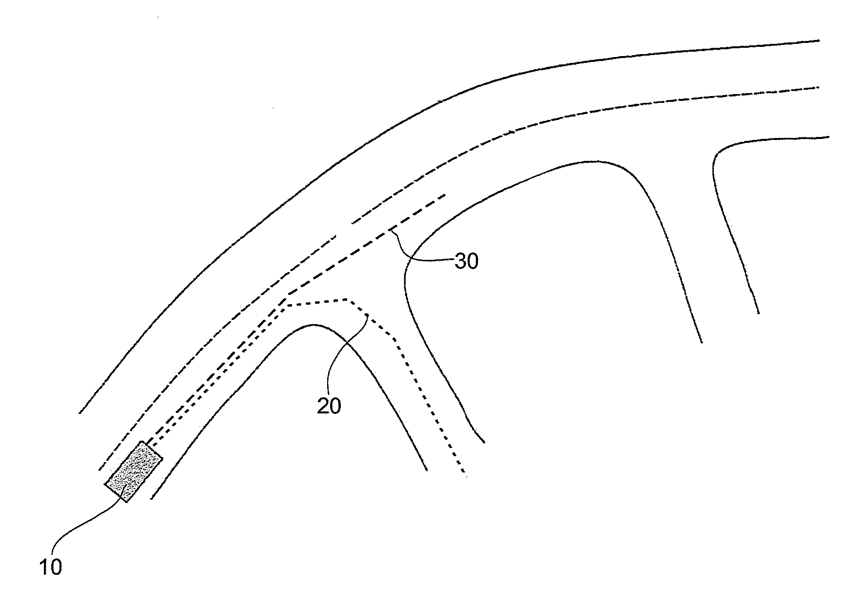
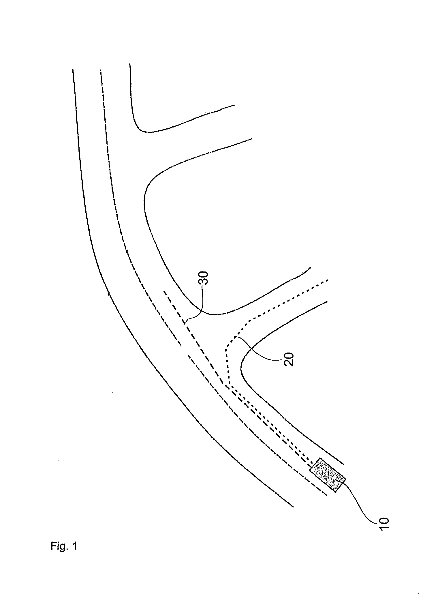
[0043]FIG. 1 shows the basic situation of a vehicle 10 with a view from above. Vehicle 10 is located on a main road and is approaching two intersections. The first dashed line indicates the expected route 20, which indicates the vehicle will turn at the first intersection. Expected route 20 was determined based on at least one criterion, which e. g. could be a reduced speed by vehicle 10, a negative acceleration of vehicle 10, the actuation of ...


PUM


Abstract

A process for setting the pivotal angle of the curve headlights of a vehicle at crossroads or intersections includes the steps of defininga projection distance for setting the pivotal angle; determiningthe expected vehicle route based on at least one criterion; limitingthe projection distance when approaching a crossroad or intersection to the distance between the vehicle and the crossroad or intersection when using an expected vehicle route that involves turning at a crossroad or into an intersection; and maintaining theprojection distance without modification when using an expected route for the vehicle that does not involve turning at a crossroad or intersection.

Description

CROSS REFERENCE[0001]This application claims priority to German Patent Application No. 10 2012 103630.6, filed Apr. 25, 2012, which is expressly incorporated in its entirety by reference herein.TECHNICAL FIELD OF THE INVENTION[0002]The following concept pertains to the process for setting the pivotal angle of the curve headlights of a vehicle at crossroads or intersections.BACKGROUND OF THE INVENTION[0003]Processes such as these for setting the pivotal angle of the curve headlights of a vehicle, particularly at crossroads or intersections, are general knowledge. They are used to provide better illumination of the area in front of the vehicle for the driver. When driving around corners, for example, a pivotal angle is generally pre-determined that adjusts the curve headlights to the radius of the curve, thereby better illuminating the road in front of the vehicle. It is also known, as described e.g. in DE 10 2008 054 005 A1, that the pivotal angle is also set at crossroads or interse...

Claims


Application Information

Patent Timeline
Patent Type & Authority Applications(United States)
IPC IPC(8): B60Q1/076
CPCB60Q1/076B60Q1/12B60Q2300/114B60Q2300/142B60Q2300/32B60Q2300/336B60Q2300/112
Inventor KUBITZA, BORIS
Owner HELLA KG HUECK & CO
Why Eureka
Try Eureka