System and Method of Water Recovery Including Automated Monitoring and Control

Active Publication Date: 2013-12-05
SUN TO WATER TECHNOLOGLIES LLC
View PDF2 Cites 5 Cited by
  • Summary
  • Abstract
  • Description
  • Claims
  • Application Information

AI Technical Summary

Benefits of technology

[0034]Other aspects of the invention include a construction for a desiccant cartridge, a method of selectively controlling air flow through a chamber for a water recovery device, a modular construction for a water recovery device utilizing easily assembled components, a method for controlling a charging cycle of a water recovery apparatus including the use of algorithms to optimize operation, a method for controlling an extraction cycle of a water recovery apparatus including the use of algorithms to optimize operation, a method of operating a water recovery device including the use of algorithms to minimize energy usage, a method of operating a water recovery device including the use of algorithms to provide an even and continuous operation of a water recovery device, and a method of controlling operation of a water recovery device incorporating a plurality of control inputs including various sensors, weigh scales, and flow meters.
[0035]Yet further aspects of the invention include a water recovery device utilizing multiple energy sources to power an extraction cycle, a method of determining optimal formulations for a liquid desiccant solution used within a water recovery device, a construction for a desiccant media including a formulation for a liquid desiccant solution, a water recovery device including configurable desiccant media cartridges, a method for selective and dynamic control of a liquid desiccant solution used within a water recovery device, a water recovery device including insulating and sealing components that effectively isolate airflow through the device and otherwise provide optimal temperature and pressure conditions within a chamber of the device, and a method for determining an optimal initial desiccant formulation of a water recovery device considering relevant geographical data corresponding to the geographical location where the device is to be installed.
[0036]Yet further aspects of the invention include a method of manufacturing a modular water recovery system. Generally, according to this method, the modular components which make up the system greatly simplify and allow repeatability for manufacturing on a large scale. For example, the desiccant trays can be made from a single mold, which therefore prevents having to specially modify or change desiccant trays among different installations. The particular capacity of an installation is therefore simply a function of the particular number and shaped configuration of the trays. Similarly, the means to seal gaps between connected desiccant trays can be a single gasket design, which again greatly simplifies manufacturing on a large scale. With respect to the manifolds that are used to interconnect the desiccant tray stack (s) to the condenser by the various inlet and exhaust lines, these manifolds can be designed so that only a friction fit is required to seal the manifolds with the lines. Also, the particular components in the inlet and exhaust lines to include the various baffles and valves may also be designed so that only a friction fit is required to seal these components with their adjacent lines. Therefore, there is no assembly or manufacturing requirement to separately seal or join these components.

Problems solved by technology

Potable water is often difficult to obtain in many locations throughout the world.
In arid climates, there is simply a shortage of water and if water is available, it may difficult to make the water potable water without extensive water treatment resources.
Even in wet climates, potable water may be in short supply because of the lack of treatment equipment.
Unfortunate events such as war or general political conflict within a country often results in diminished infrastructure that would normally have the capability to provide potable water.
However, a misting dev

Method used


Image

  • System and Method of Water Recovery Including Automated Monitoring and Control
  • System and Method of Water Recovery Including Automated Monitoring and Control
  • System and Method of Water Recovery Including Automated Monitoring and Control

Examples


Example

DETAILED DESCRIPTION OF THE DRAWINGS

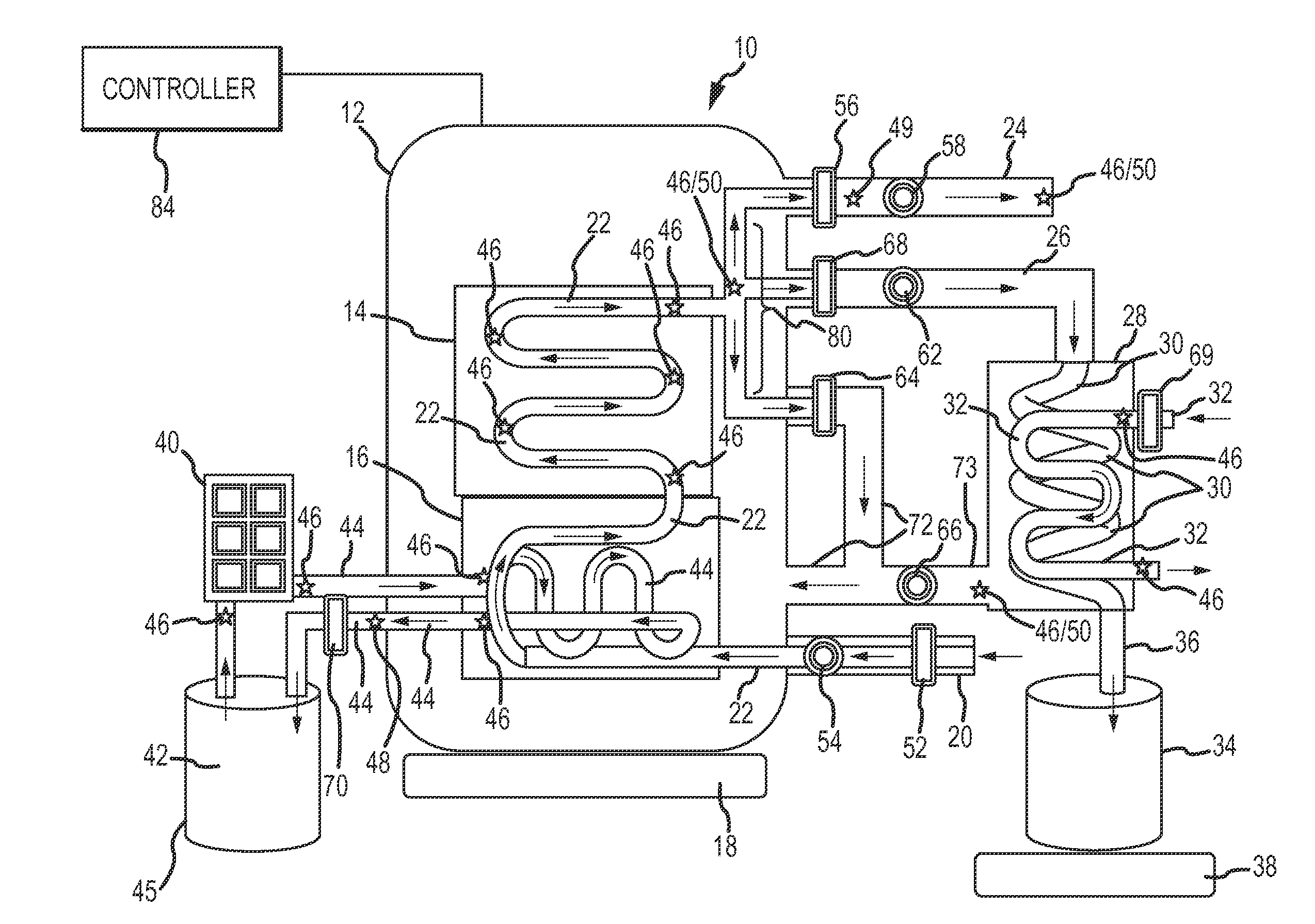
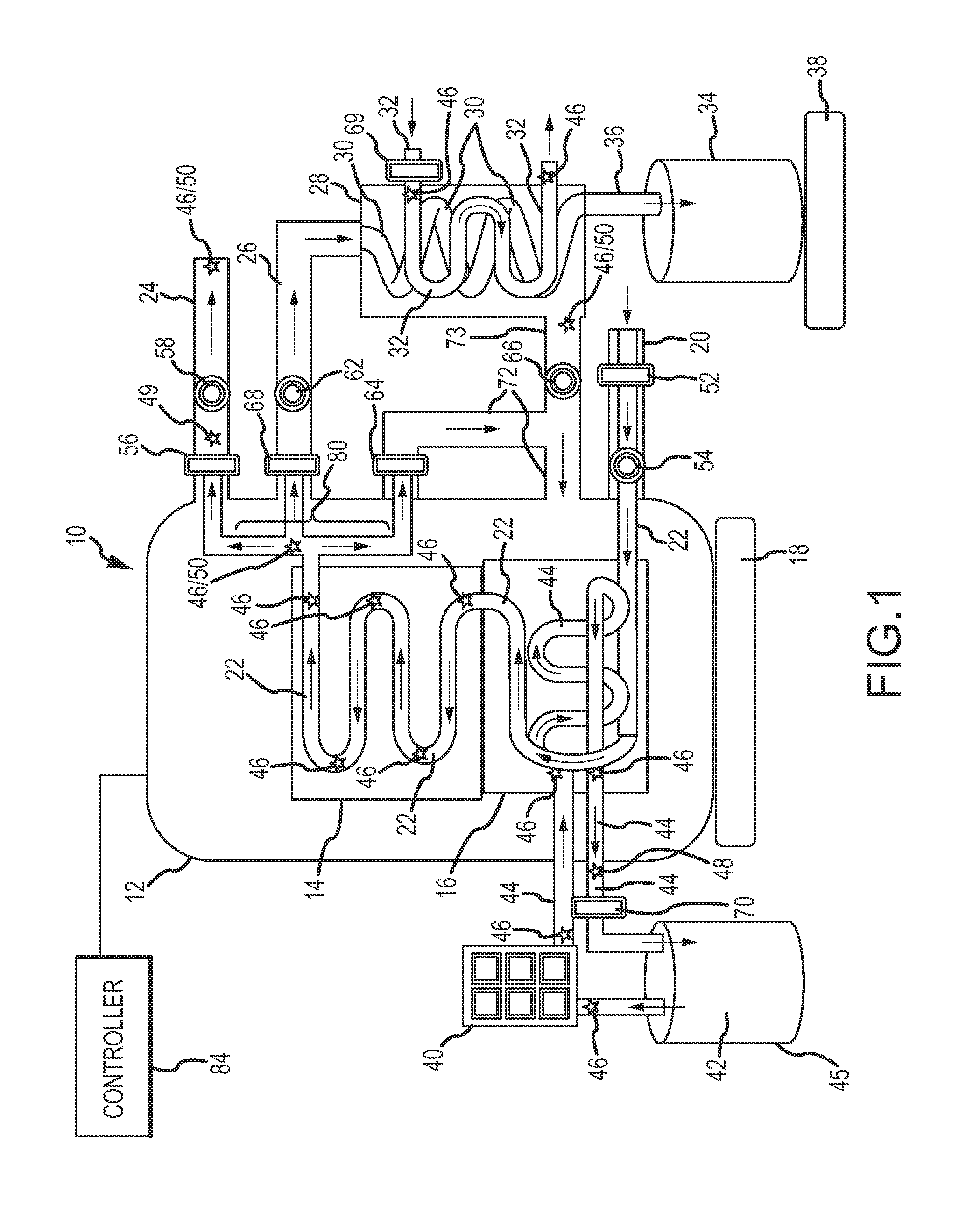
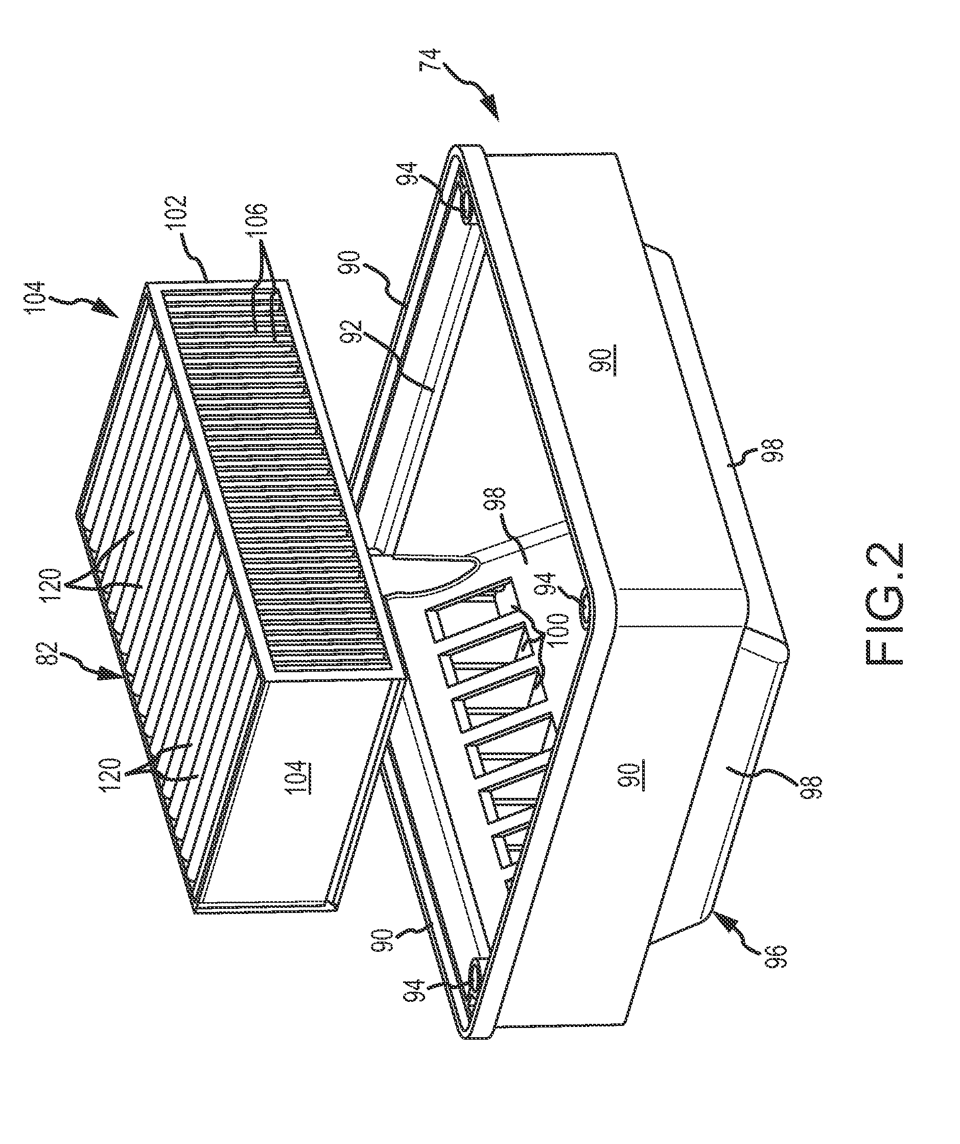
[0078]Referring to FIG. 1, a schematic diagram is shown for purposes of illustrating the major functional components of a device of the system. Specifically, the device 10 includes a housing 12 that defines therein an interior space or chamber for receiving a flow of air to remove water vapor from the airstream. The chamber is more specifically defined as including a desiccant stack 14 including a plurality of desiccant trays 74 (see FIG. 2) that each holds a desiccant media material.

[0079]Each of the trays 74 have a quantity of a liquid desiccant solution placed in contact with the desiccant media material that wicks or absorbs the solution, as set forth further below with respect to the description of the FIGS. 2-4. The device 10 further includes one or more heat exchanger assemblies 16 for providing heat to the chamber. A weigh scale 18 is used to monitor the mass of water vapor that is collected from the airstream during a charge cycle, as wel...


PUM

PropertyMeasurementUnit
Temperatureaaaaaaaaaa
Relative humidityaaaaaaaaaa
Photovoltaic performanceaaaaaaaaaa

Abstract

A device recovers water from an ambient airstream. The device includes a chamber having a group of trays that hold respective amounts of liquid desiccant. A foam media element in each tray absorbs the desiccant to increase an exposed surface of the desiccant to the airstream. Fans and valves are used to control airflow through the device. A charge cycle circulates air through the device to remove water vapor from the airstream. A subsequent extraction cycle removes water collected in the liquid desiccant by a condenser communicating with the chamber. An integral heat exchanger adds heat to the chamber during the extraction cycle. A controller is used to integrate and control device operation. The desiccant trays may be selectively configurable in an array to best suit the intended installation. The trays may be arranged in column and row configurations, along with adjustable airflow patterns between each of the trays. User interfaces are provided to monitor and control operation of the device.

Description

CROSS REFERENCE TO RELATED APPLICATION[0001]The present application claims the benefits of and priority, under 35 U.S.C. §119(e), to U.S. Provisional Application Ser. No. 61 / 655,316, filed Jun. 4, 2012, entitled “WATER RECOVERY SYSTEM AND METHOD,” herein incorporated by reference in its entirety for all purposes.FIELD OF THE INVENTION[0002]The invention relates to a water recovery system and method of recovering water from ambient air. More particularly, the invention relates to an apparatus / device and method using a desiccant solution to extract water from the air, and then separating the water from the desiccant. The recovered water may be treated to obtain potable water. A byproduct of the system and method is a stream of dehumidified air that may be used for conditioning an interior airspace within a man-made structure.BACKGROUND OF THE INVENTION[0003]Potable water is often difficult to obtain in many locations throughout the world. In arid climates, there is simply a shortage o...

Claims


Application Information

Patent Timeline
IPC IPC(8): F24F3/14
CPCF24F3/1417B01D53/263B01D53/0454B01D53/18B01D53/26B01D53/28F25B17/02F25B37/00F25B43/00F25D21/14Y02B30/62Y10T29/49396Y10T29/49826
Inventor BECZE, CHARLESBALL, JAMES
Owner SUN TO WATER TECHNOLOGLIES LLC
Why Eureka
Try Eureka