Vehicular air-conditioning system

a technology of air-conditioning system and vehicle, which is applied in vehicle components, vehicle heating/cooling devices, railway heating/cooling, etc., and can solve problems such as sound, and increased pressure at the scroll casing outlet of the blower

a technology of air-conditioning system and vehicle, which is applied in vehicle components, vehicle heating/cooling devices, railway heating/cooling, etc., and can solve problems such as sound, and increased pressure at the scroll casing outlet of the blower

US20130319630A1Inactive Publication Date: 2013-12-05DENSO CORP

Image

  • Vehicular air-conditioning system
  • Vehicular air-conditioning system
  • Vehicular air-conditioning system

Examples


Embodiment Construction

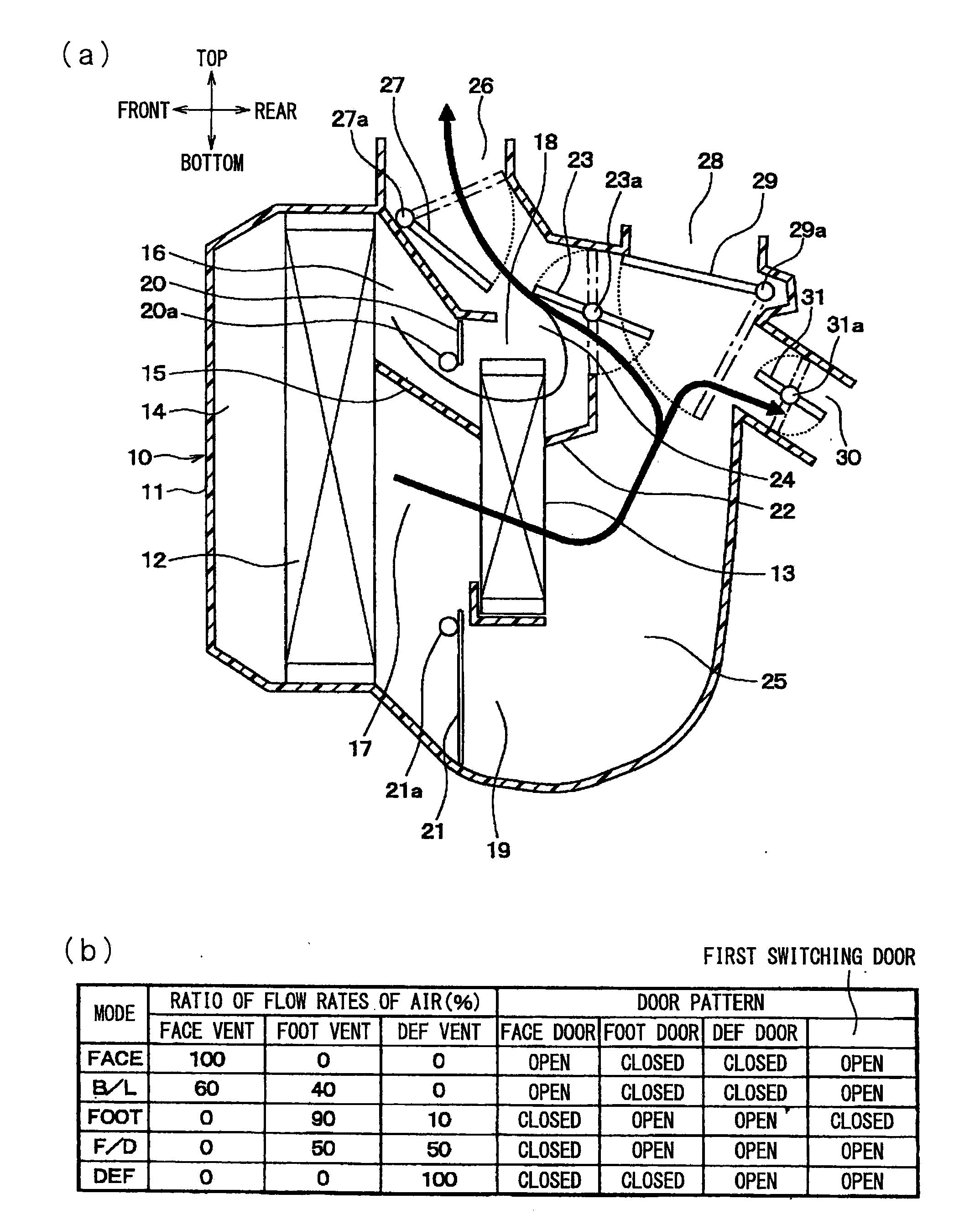
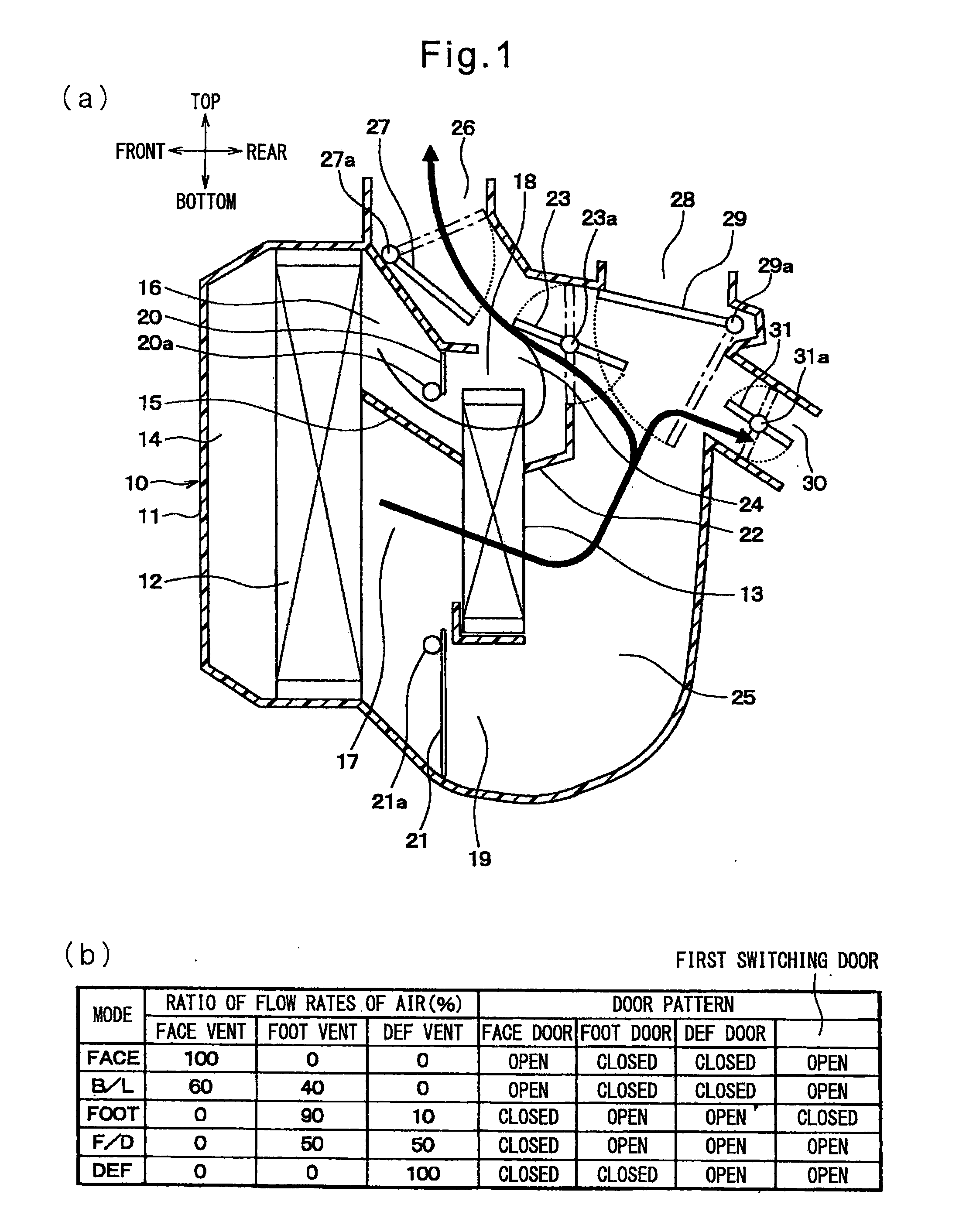
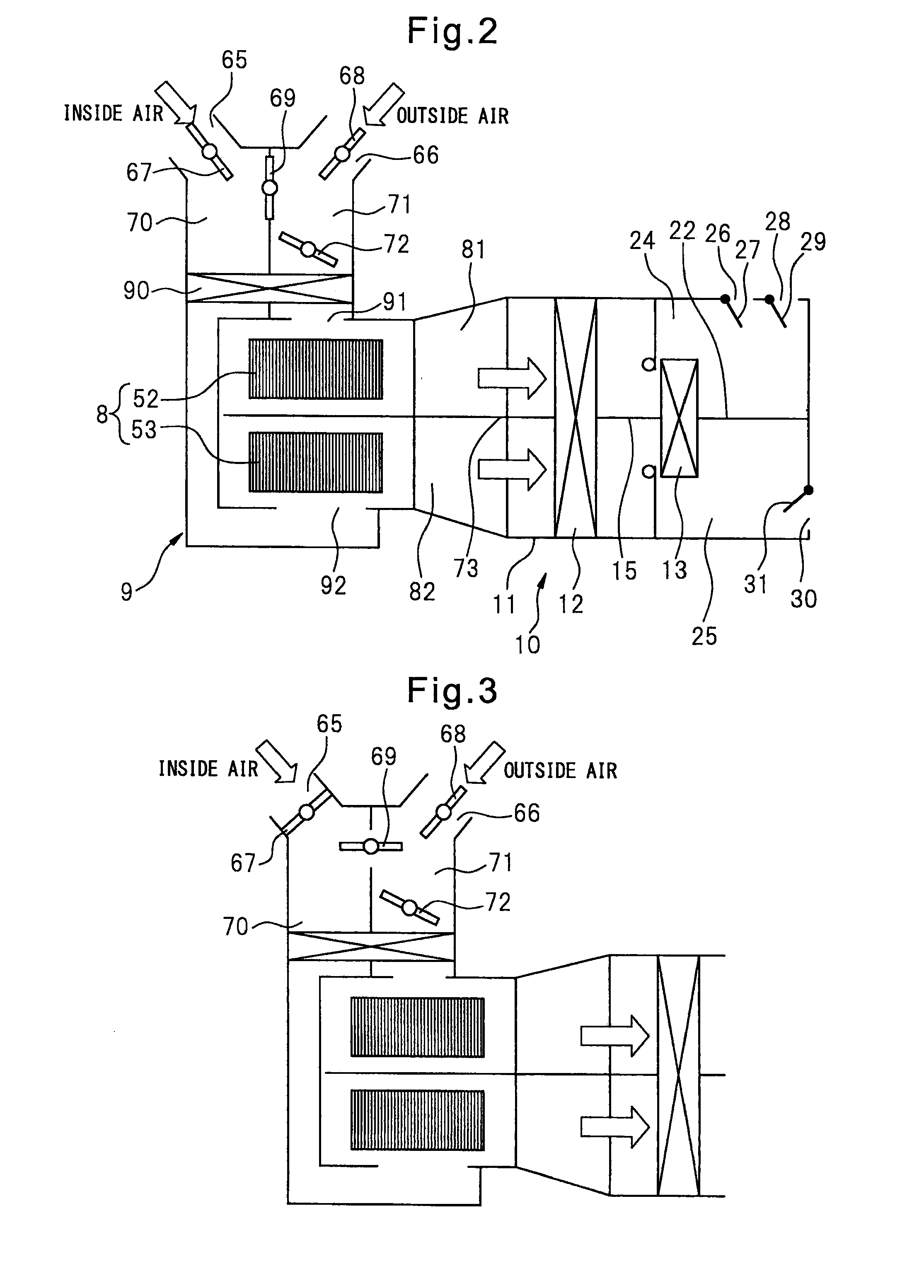
[0036]The present invention will be understood more clearly while considering the description of embodiments of the present invention given with reference to the attached drawings as explained below. Below, embodiments of the present invention will be explained with reference to the drawings. In the embodiments, parts of the same configuration are assigned the same reference notations and their explanations are omitted. Parts of the same configuration as the prior art as well are assigned the same reference notations and their explanations are omitted. FIG. 2 is a schematic explanatory view of an inside / outside air suction FOOT mode in an embodiment of the present invention. FIG. 3 is a schematic explanatory view of an outside air suction FOOT mode in an embodiment of the present invention. FIG. 4 is a schematic explanatory view of an inside / outside air suction FOOT mode in a modification of a suction port switching door of an embodiment of the present invention. The vehicular air-c...


PUM


Abstract

An air conditioning device for a vehicle, provided with: an air blower unit having a first introduction path and a second introduction path through which inside air or outside air is sucked into an upper fan and a lower fan by switching between switching doors; and an air conditioning unit for discharging air into the vehicle interior. The air conditioning device for a vehicle is characterized in that the first introduction path is an introduction path into which only the outside air is introduced when the inside air and the outside air are sucked separately and in that an outside air amount adjustment mechanism for limiting the amount of delivery of the outside air according to the speed of the vehicle is provided in the first introduction path or at a position downstream thereof to reduce the generation of wind noise at a defroster opening or a face opening.

Description

TECHNICAL FIELD[0001]The present invention relates to a vehicular air-conditioning system which is designed to suppress the occurrence of a whistling sound due to slight door opening and to prevent detraction of comfort in air blown in a passenger compartment due to an increase in the flow rate of air due to the ram pressure (pressure of air due to movement of vehicle).BACKGROUND ART[0002]At the time of the FOOT (foot) mode which blows air-conditioned air toward the feet of the driver and passengers, sometimes an extremely large amount of air-conditioned air is distributed through the FOOT vents and a slight flow rate of air is blown through the DEF (defroster) vents to the vehicle windshield side to defog the vehicle windshield. In such a FOOT mode, sometimes the vent mode door is operated to a slightly open position. In this case, the flow of air is rapidly throttled by the slight clearances of the DEF vents and FACE vents and air is ejected through the slight clearances at a fast...

Claims


Application Information

Patent Timeline
05 Dec 2013
Publication
US20130319630A1
IPC
B60H1/00
CPC
B60H1/00021; B60H1/00764; B60H1/00828; B60H2001/00085
Inventors
YAMAMOTO, YUUDAI; TOYAMA, TATSUYA