Sleeve activated compressed fluid dispensing device with internal seal

a compressed fluid and seal technology, applied in liquid dispensing, single-unit apparatus, packaging, etc., can solve the problems of foam being undetected around the nipple area and possibly the fingers of users, and achieve the effect of avoiding foam on their hands

Active Publication Date: 2013-12-05
DOW GLOBAL TECH LLC
View PDF3 Cites 24 Cited by
  • Summary
  • Abstract
  • Description
  • Claims
  • Application Information

AI Technical Summary

Benefits of technology

[0008]The present invention provides a dispensing device for compressed fluids that can seal the application tube from the inside thereby resolving the problem of expandable foamable mixtures from continuing to expel from the application tube while avoiding having to insert something from outside the application tube into the end of the dispensing tube or having a rod extend through the entire barrel of the dispensing device. Moreover, certain embodiments of the present invention are capable of remotely unsealing the dispensing tube to apply a compressed foamable liquid and then automatically sealing the application end of the dispensing tube at the will of a user. Even more, pressure from expanding foam formulation within a dispensing tube can automatically direct a plug to seal the tube at the will of the user without requiring a separate means (for example, a spring) for directing a plug to seal the dispensing tube. With the present invention, a user can avoid having to put their hands near the dispensing tube to seal or unseal it and thereby can avoid getting foam on their hands.

Problems solved by technology

One challenge with spray foam is that residual foamable formulation in the application tube of the dispenser is free to continue to expand after applying spray foam formulation to a location.
The expanding residual foamable liquid can drip from the application tube to create unintended messes.
Inserting a nipple into the end of an application tube from outside the application tube will itself displace fluid out from the application tube around the nipple resulting in foam being undesirably disposed around the nipple area and possibly the fingers of a user.

Method used


Image

  • Sleeve activated compressed fluid dispensing device with internal seal
  • Sleeve activated compressed fluid dispensing device with internal seal
  • Sleeve activated compressed fluid dispensing device with internal seal

Examples


Embodiment Construction

[0016]“And / or” means “and, or as an alternative”. “Multiple” means “two or more”. All ranges include endpoints unless otherwise indicated.

[0017]Applicants anticipate that aspects of any embodiment are combinable in an unlimited fashion with any aspects of any other embodiments unless such a combination is physically impossible.

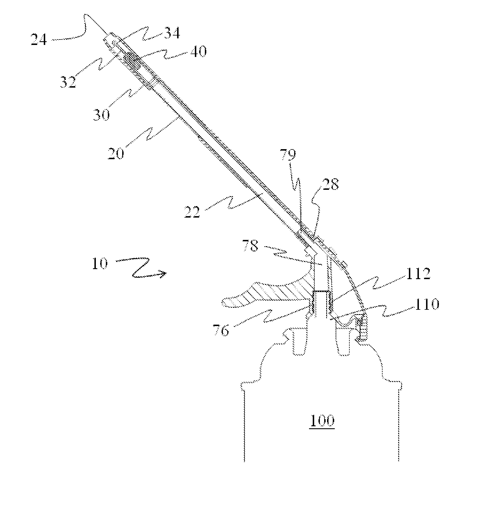
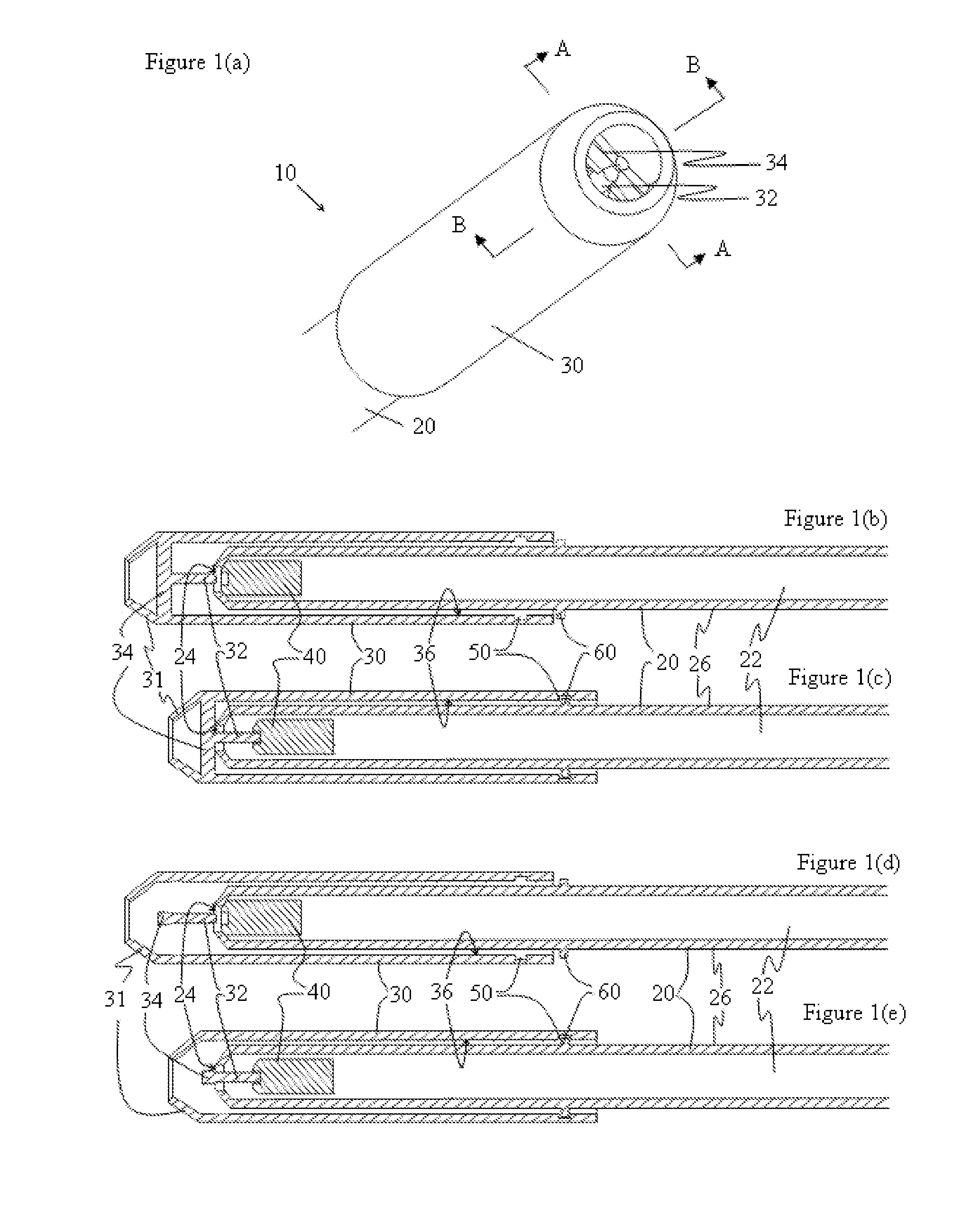
[0018]The present invention is a dispensing device for dispensing compressed fluids from a can through a valve stem of the can. In the broadest scope of the invention, the type of compressed fluid is unlimited and can include both liquids and gases. However, the present invention is particularly useful for dispensing compressed foamable formulations that are in liquid form. Foamable formulations typically comprise a mixture of matrix material and blowing agent that is held under sufficient pressure to preclude expansion of the blowing agent until foaming is desired. Upon release of the pressure the blowing agent can expand within the matrix material to create ...


PUM


Abstract

A dispensing device for dispensing compressed fluid from a can through a valve stem of the can has a hollow tube with a channel extending through it from an entrance end to an opposing dispensing end, a connector defining a conduit therethrough that is in fluid communication with the channel of the hollow tube and that attaches to a valve stem of a can, a plug located within the channel of the hollow tube that forms a sealing configuration within the channel when pressed towards the dispensing end of the channel, and a sleeve that wraps at least partially around the hollow tube and that has a protrusion that upon activating the sleeve extends through the dispensing end of the hollow tube and prevents the plug from establishing a sealing configuration with the hollow tube.

Description

BACKGROUND OF THE INVENTION[0001]1. Field of the Invention[0002]The present invention relates to a dispensing device for dispensing compressed fluid from a can and a dispensing system comprising the dispensing device and can.[0003]2. Description of Related Art[0004]Dispensing fluid, particularly foamable fluid, from a compressed can is useful for many do-it-yourself products. One such product is spray foam for sealing and thermal insulation applications. Spray foam is available as foamable liquid under pressure in a can. It is common to dispense the foamable liquid through an application tube (or straw) attached to a valve or valve stem on the can. Upon release from the pressurized can the foamable liquid expands into foam and fills gaps and / or provides a thermal insulating seal. Foamable liquids include foamable latex and foamable polyurethane formulations.[0005]One challenge with spray foam is that residual foamable formulation in the application tube of the dispenser is free to c...

Claims


Application Information

Patent Timeline
Patent Type & Authority Applications(United States)
IPC IPC(8): B65D83/00
CPCB65D83/303B05B1/3046B05B11/0029B65D83/201B65D83/207B65D83/345B65D83/46B05B11/1053
Inventor HOAGLAND, MARY M.SCHULZ, PETER J.SILER, CHRISTOPHER J.
Owner DOW GLOBAL TECH LLC
Why Eureka
Try Eureka