Light emitting device

a technology of light emitting device and led lamp, which is applied in the direction of semiconductor devices for light sources, lighting support devices, lighting and heating apparatus, etc., can solve the problems of high cost of traditional led lamps, limited application and challenges of leds or similar light emitting units to lamps for lighting, and unsuitable arrangement described above to substitute for traditional lamps with wide lighting angles. , to achieve the effect of uniform lighting performance, sufficient lighting intensity and flexibility

Active Publication Date: 2013-12-05
EPISTAR CORP
View PDF1 Cites 11 Cited by
  • Summary
  • Abstract
  • Description
  • Claims
  • Application Information

AI Technical Summary

Benefits of technology

The present invention relates to a light emitting device with high reliability, high lighting efficiency, and low cost. The device comprises a transparent substrate and multiple LED chips with multiple light emitting surfaces emitting light in omni-direction. The device provides sufficient lighting intensity and uniform lighting performance with adjustable brightness. The arrangement of the substrates allows for more flexibility in applications. Overall, the present invention provides a light emitting apparatus with improved lighting efficiency and flexibility.

Problems solved by technology

Practically, there are still limitations and challenges for applying LEDs or similar light emitting units to lamps for lighting.
This kind of arrangement described above was not appropriate to substitute for traditional lamps with wide lighting angles.
Therefore the cost of the tradition LED lamp was high and the benefit for saving energy was insufficient.
Thereby, the flexibility of disposing LED chips was limited.
For example, when the substrates were non-planar, the light generated by the LED chips deposited on the substrates would be shielded or blocked accordingly, which was unfavorable for reducing power consumption and costs of traditional LED lamps.

Method used


Image

  • Light emitting device
  • Light emitting device
  • Light emitting device

Examples


Embodiment Construction

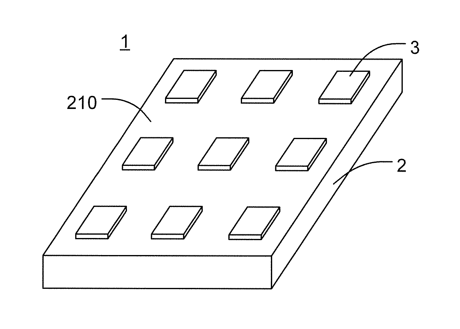
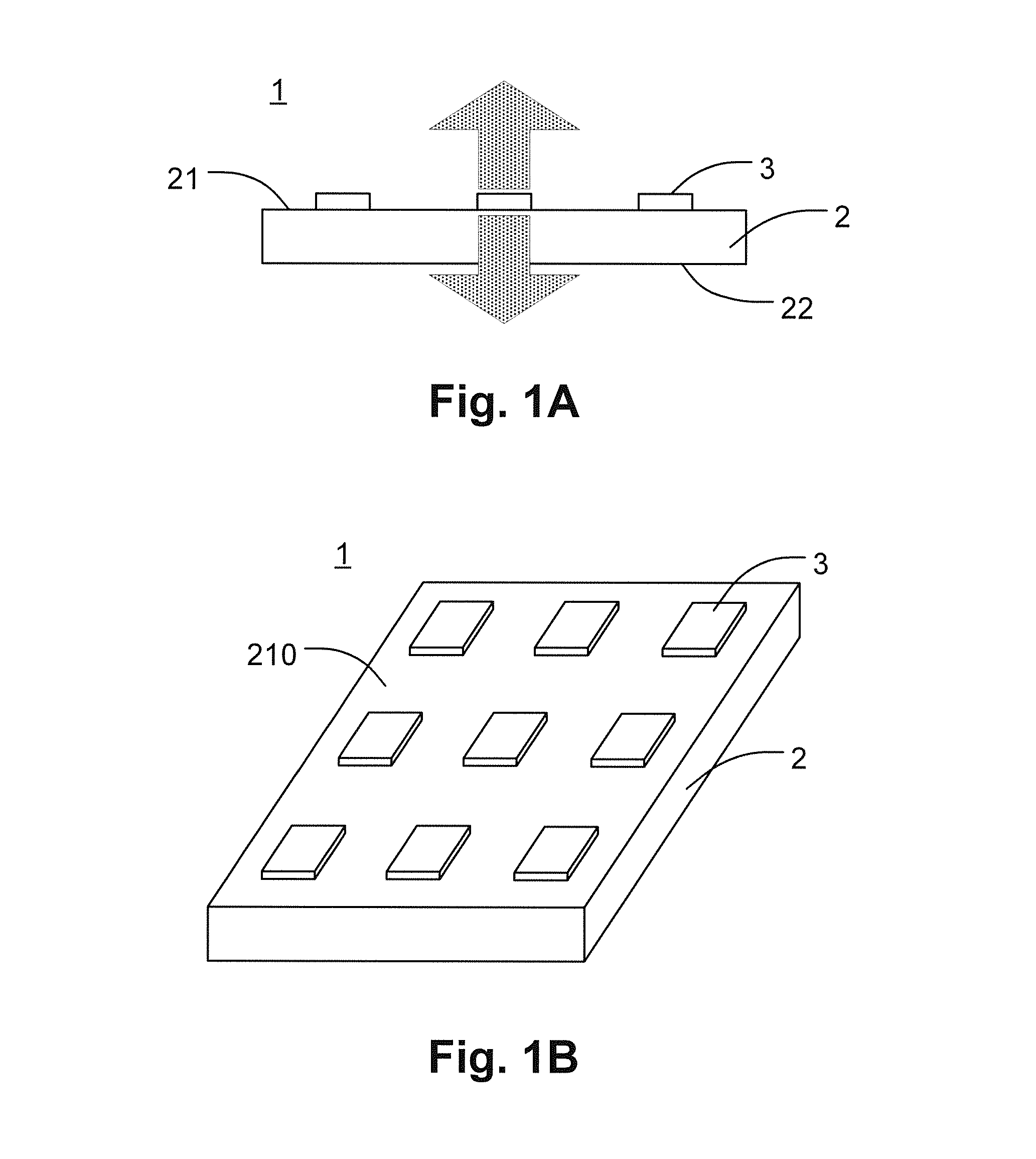
[0024]As shown in FIGS. 1A and 1B, the first embodiment of the present invention discloses a light emitting device 1 comprising a transparent substrate 2 which light can pass through, a support surface 210, a first main surface 21, a second main surface 22, and at least one LED chip 3 emitting light omni-directionally.

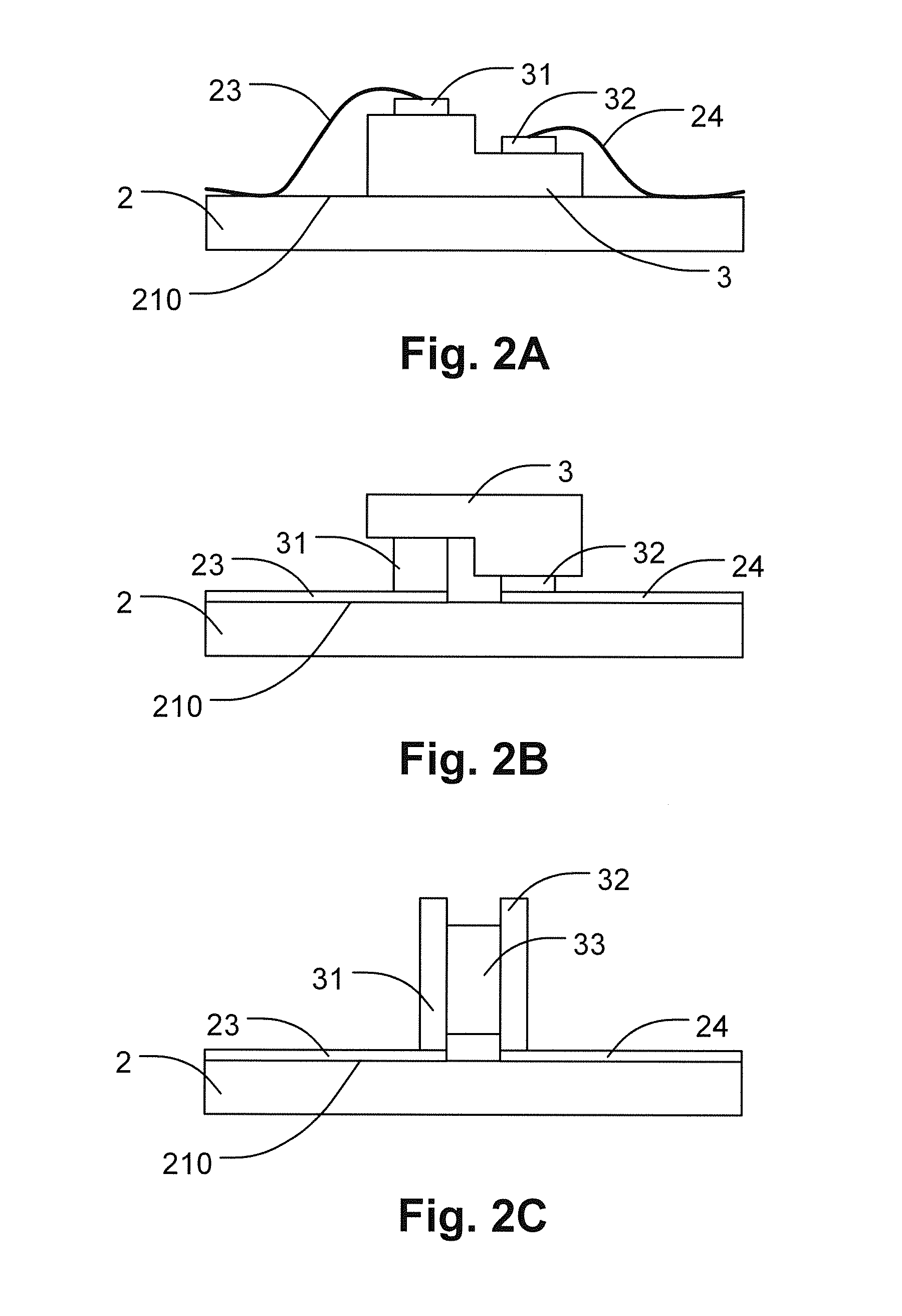
[0025]Wherein the number of the LED chips 3 deposited on the support surface 210 of the sheet-shaped substrate 2 according to the embodiment is 9, and the embodiment arranges the LED chips 3 as a 3×3 matrix. The LED chip 3 comprises multiple light emitting surfaces, and one of the light emitting surfaces 34 and the support surface 210 form the illuminant first main surface 21 of the light emitting device 1. Because the light emitting angle of the LED chip 3 is wider than 180°, at least a portion of light emitted from the LED chip 3 will penetrate into the substrate 2 from the support surface 210 and pass through the substrate 2. Then the incident light in the substrate...


PUM


Abstract

The present invention relates to a light emitting device comprising a transparent substrate which light can pass through and at least one LED chip emitting light omni-directionally. Wherein the LED chip is disposed on one surface of the substrate and the light emitting angle of the LED chip is wider than 180°, and the light emitted by the LED chip will penetrate into the substrate and at least partially emerge from another surface of the substrate. According to the present invention, the light emitting device using LED chips can provide sufficient lighting intensity and uniform lighting performance.

Description

FIELD OF THE INVENTION[0001]The present invention relates to a light emitting device comprising semiconductor light emitting diode (LED) chips, and particularly to a light emitting device comprising at least one LED chip which emits light omni-directionally, and a light emitting apparatus using same.BACKGROUND OF THE INVENTION[0002]In the field of lighting technology, the development trends for light sources are low cost, environmental friendliness, and power saving in order to acquire better lighting performance under the condition of consuming less power. These trends make LEDs play an important role in the development.[0003]Practically, there are still limitations and challenges for applying LEDs or similar light emitting units to lamps for lighting. In the past, using LEDs as a light source called for depositing multiple LED chips on a plane and further providing an optical reflection mechanism to guide or broadcast the light emitted from the LED chips emitting light directional...

Claims


Application Information

Patent Timeline
Patent Type & Authority Applications(United States)
IPC IPC(8): H01L33/50
CPCH01L33/50H01L33/486H01L2224/48091H01L2224/49107H01L2924/3025F21K9/232H01L24/14H01L24/16H01L24/48H01L24/49H01L33/007H01L33/44H01L33/507H01L33/62H01L2224/14051H01L2224/16225H01L2224/32225H01L2224/48137H01L2224/73204H01L2224/73265H01L2224/83385H01L2224/8592H01L2924/00011H01L2924/00014H01L2924/01322H01L2924/12041H01L2924/19107H01L2224/48227F21Y2107/00F21Y2115/10H01L2224/1403H01L2224/16H01L2224/48465H01L25/0753H01L2224/45147H01L2224/45124H01L2924/00H01L2224/13099H01L2224/45099H01L2924/01015H01L33/02H01L33/36H01L33/505F21K9/237H01L27/156F21V15/01F21K9/235F21V21/00F21V21/14H01L33/508F21V29/85F21V3/02F21V17/10F21V23/06
Inventor PU, CHI-CHIHLEE, CHEN-HONGYEH, SHIH-YUCHENG, WEI-KANGPAN, SHYI-MINGHONG, SIANG-FUHUANG, CHIH-SHUWANG, TZU-HSIANGTANG, SHIH-CHIEHYANG, CHENG-KUANG
Owner EPISTAR CORP
Why Eureka
Try Eureka