
Electrical Power Status Indicator

a technology of status indicators and electric appliances, applied in the integration of power network operation systems, relays, sustainable buildings, etc., can solve the problems of cumbersome current implementations, delay the operation of electrical appliances, and high electricity prices

Active Publication Date: 2013-12-05
CENTURYLINK INTPROP
View PDF14 Cites 25 Cited by
  • Summary
  • Abstract
  • Description
  • Claims
  • Application Information

AI Technical Summary

Benefits of technology

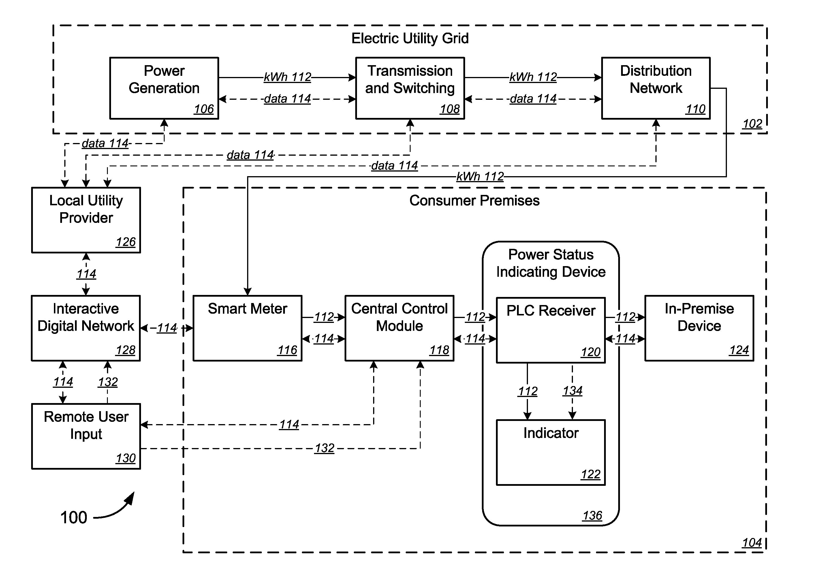
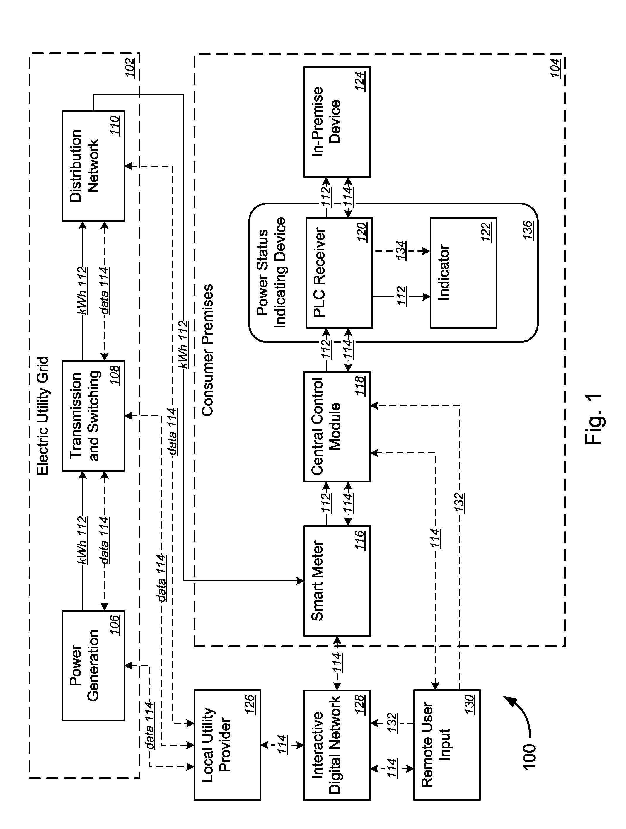
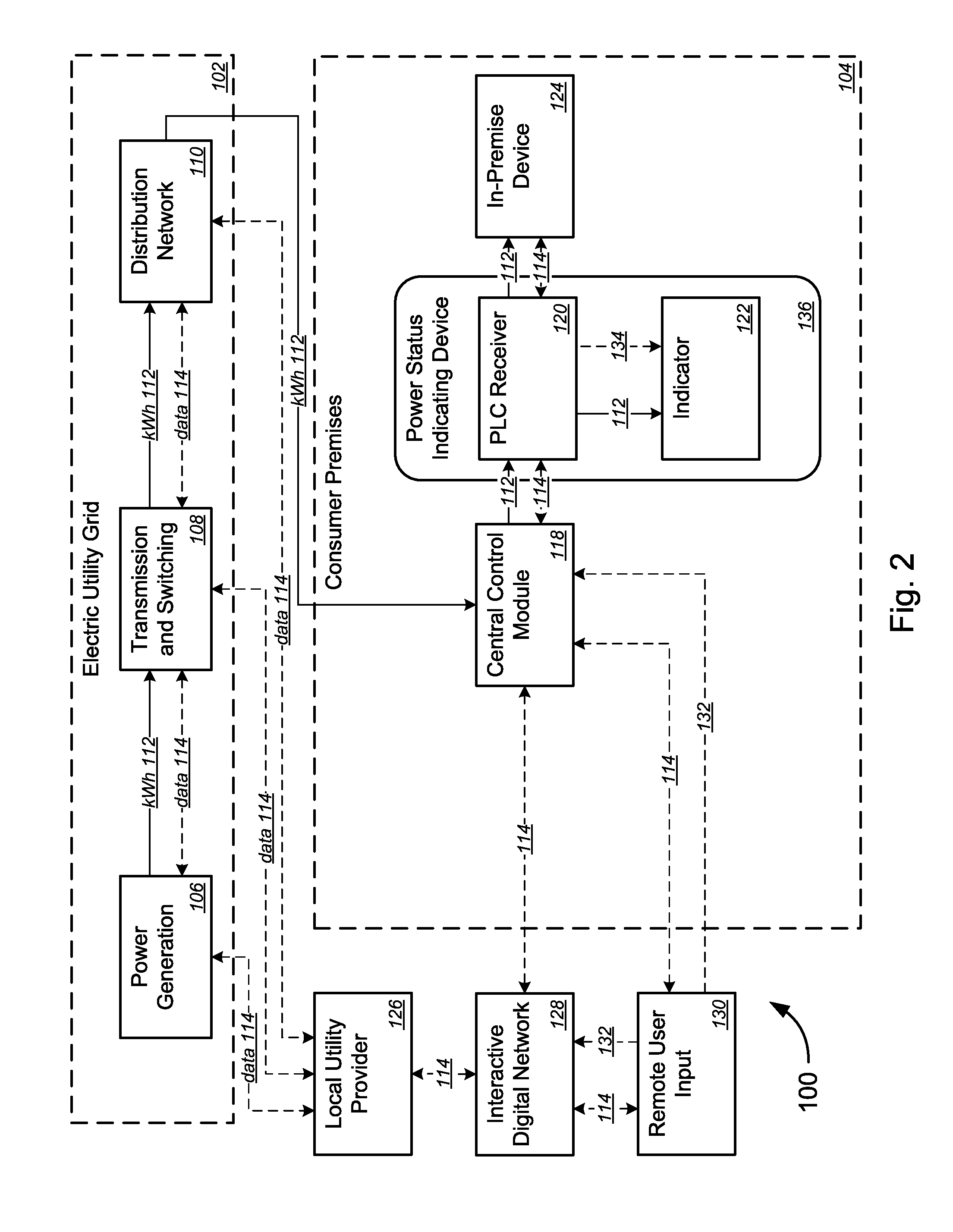
The patent describes tools and techniques for electricity consumers to monitor the status of their utility's power grid and adjust their electricity consumption accordingly. This is achieved through the use of a power status-indicating electrical receptacle that continuously or periodically retrieves and interprets power status data from a centralized control module. The receptacle can include an indicator that is activated based on the power status data, such as a luminary indicator, a display screen, or an audio indicator. The receptacle can also adjust its power output level based on predetermined conditions, such as exceeding a power consumption threshold or being a member of a utility billing tier. The power status-indicating electrical receptacle can also communicate with other appliances connected to the home network and adjust their power usage in response to the transmitted electrical signals. Overall, the patent provides tools for consumers to better manage their electricity consumption and help balance the grid.

Problems solved by technology

For example, a consumer might choose to delay the operation of an electrical appliance if she receives data indicating that the price of electricity is particularly high at that moment.
Current implementations that are available to consumers are cumbersome, however.
The devices are also complex and often provide detailed information that may be difficult for consumers to interpret directly.
Consequently, the current devices are not able to provide effective communication or usage to the consumer.
Furthermore, Smart Grid data is limited for use by Smart Appliances that are programmed to interpret the data and adjust consumption accordingly.

Method used


Image

  • Electrical Power Status Indicator
  • Electrical Power Status Indicator
  • Electrical Power Status Indicator

Examples


Embodiment Construction

[0024]While various aspects and features of certain embodiments have been summarized above, the following detailed description illustrates a few exemplary embodiments in further detail to enable one of skill in the art to practice such embodiments. The described examples are provided for illustrative purposes and are not intended to limit the scope of the invention.

[0025]In the following description, for the purposes of explanation, numerous specific details are set forth in order to provide a thorough understanding of the described embodiments. It will be apparent to one skilled in the art, however, that other embodiments of the present may be practiced without some of these specific details. In other instances, certain structures and devices are shown in block diagram form. Several embodiments are described herein, and while various features are ascribed to different embodiments, it should be appreciated that the features described with respect to one embodiment may be incorporate...


PUM


Abstract

An electrical power status-indicating device for integration with a Smart Grid network. The device comprises an electrical receptacle installed within a wall of a consumer premises, a communication module for retrieving and interpreting power status data from a centralized control module, and at least one indicator activated by the communication module, with activation based at least in part on the status data. In some embodiments, the device may comprise a power pass-through device for receiving at least one in-premise electronic device, and / or a light switch in communication with a lighting unit.

Description

COPYRIGHT STATEMENT[0001]A portion of the disclosure of this patent document contains material that is subject to copyright protection. The copyright owner has no objection to the facsimile reproduction by anyone of the patent document or the patent disclosure as it appears in the Patent and Trademark Office patent file or records, but otherwise reserves all copyright rights whatsoever.FIELD[0002]The present disclosure is related to technology for managing electric energy consumption. It is particularly concerned with systems for enabling electricity consumers to monitor a status of a utility's electric power grid and to adjust their electric power consumption accordingly.BACKGROUND[0003]Technological advancements for transmission systems and infrastructures, such as the Smart Grid, allow for a two-way communication of power grid-related data between electric utility companies and their customers. Such data, which may reflect the supply and consumption of electricity at the utility ...

Claims


Application Information

Patent Timeline
Patent Type & Authority Applications(United States)
IPC IPC(8): H01H35/00
CPCH01H2300/03H02J13/00007H02J13/00036Y02B90/20Y04S20/14Y04S40/121Y02B70/30Y04S20/20
Inventor COOK, CHARLES IVAN
Owner CENTURYLINK INTPROP
Learn More