Detecting method and device for touch screen
a technology of touch screen and detection method, which is applied in the direction of instruments, computing, electric digital data processing, etc., can solve the problems of inability to easily determine, touch may not be detected, and the change in the detected signal
- Summary
- Abstract
- Description
- Claims
- Application Information
AI Technical Summary
Benefits of technology
Problems solved by technology
Method used
Image


Examples
first embodiment
[0070]Accordingly, in the best mode of the invention, different phase differences are adopted at different electrodes so as to delay the detecting signal. For example, a plurality of phase differences are decided at first. When each set of driving electrodes are provided the driving signal, the signal is measured based on each phase. The phase difference on which the largest one of the measured signals stands closest approaches the phase difference between the signal before being provided to the driving electrodes and the signal after being received by the detecting electrodes, called the closest phase difference. The signal measurement could be to select one of the detecting electrodes to measure based on each phase difference, or select many or all detecting electrodes to measure based on each phase difference. The closest phase difference is determined based on the total amount of signals of the many or all detecting electrodes. Accordingly, the closest phase difference of each s...
second embodiment
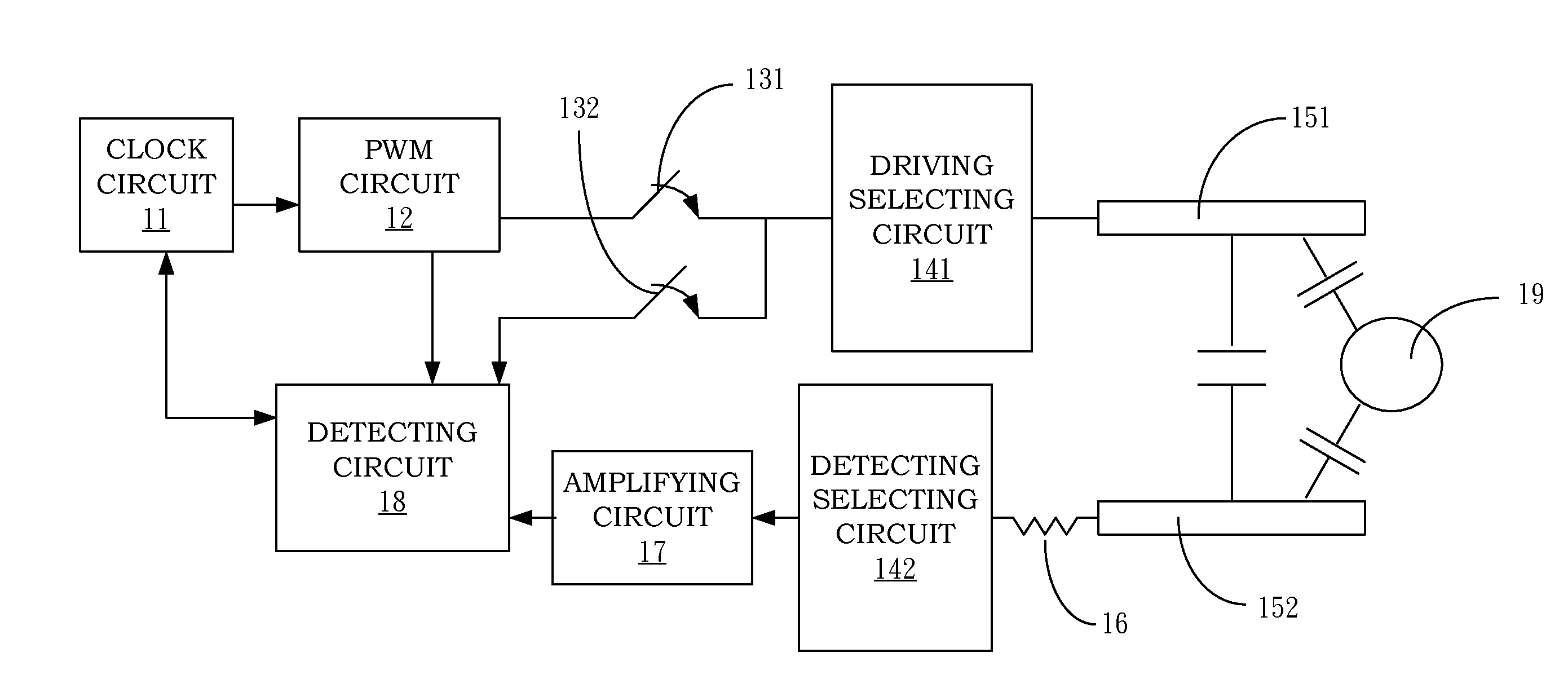
[0085]In one second embodiment of the invention, signals are measured by a control circuit, and signals of each detecting electrode are measured via a variable resistor, wherein the impedance of the variable resistor is controlled by the control circuit based on each set of driving electrodes. For example, one set of the driving electrodes could be selected as the base electrodes firstly, and others of the electrodes are called the non-base electrodes. At first, a plurality of preset impedances are set, and when one or more base electrodes are provided the driving signal, signals of one detecting electrode are measured, or sum of the plurality or all of detecting electrodes are measured as a level signal. In addition, the level signal could be within a preset working range rather than the best or largest signal. In other words, any preset impedance which can make the level signal within the preset working range could be the level impedance of the base electrode. Next, when each set ...
third embodiment
[0088]In the invention, signals are measured by a control circuit. Signals of each set of detecting electrodes are measured via a detecting circuit (e.g. a integrator), and the control circuit controls the amplification factor of the detecting circuit based on each set of driving electrodes. For example, one set of the driving electrodes are selected as the base electrode, and other electrodes are called as non-base electrodes. At first, a plurality of preset impedances are set, and when one or more base electrodes are provided the driving signal, signals of one detecting electrode are measured, or sum of the plurality or all of detecting electrodes are measured as a level signal. In addition, the level signal could be within a preset working range rather than the best or largest signal. In other words, any preset impedance which can make the level signal within the preset working range could be the level impedance of the base electrode. Next, when each set of the non-base electrode...
PUM
 Abstract
Description
Claims
Application Information