Electronic circuit module

a technology of electronic circuit module and circuit board, which is applied in the direction of electrical apparatus construction details, flexible screening containers, and metallic containers, etc., can solve the problems of metal cover before joining to the circuit board deformation, metal cover is not soldered to the desired position, and metal cover is not properly positioned in the height direction, so as to increase increase the stiffness of the mounting legs. , the effect of increasing the width of the bent portion

Inactive Publication Date: 2013-12-05
ALPS ALPINE CO LTD
View PDF2 Cites 13 Cited by
  • Summary
  • Abstract
  • Description
  • Claims
  • Application Information

AI Technical Summary

Benefits of technology

[0014]The mounting legs of the metal cover are bent at their bent portions from the top plate, and the mounting leg fixing portions are in contact with the lands of the circuit board and are joined to the lands. The mounting legs are formed in such a manner that when seen from the upper surface of the circuit board, the position of the bent portion is on the inner side of the position of the mounting leg fixing portion, and the width of the bent p

Problems solved by technology

However, an electronic circuit module employing a thin metal cover has a problem that the metal cover before joining to the circuit board is deformed owing to drop or external force.
When the metal cover is joined to the circuit board, and if the metal cover before joining to the circuit board is deformed, there is fear that the

Method used


Image

  • Electronic circuit module
  • Electronic circuit module
  • Electronic circuit module

Examples


first embodiment

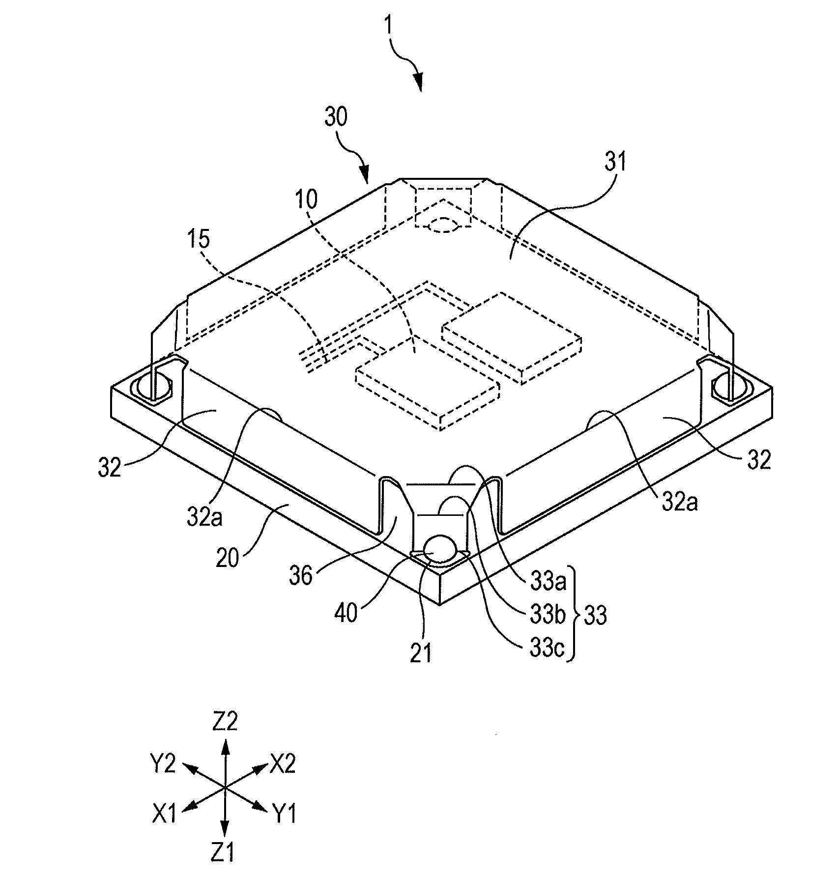
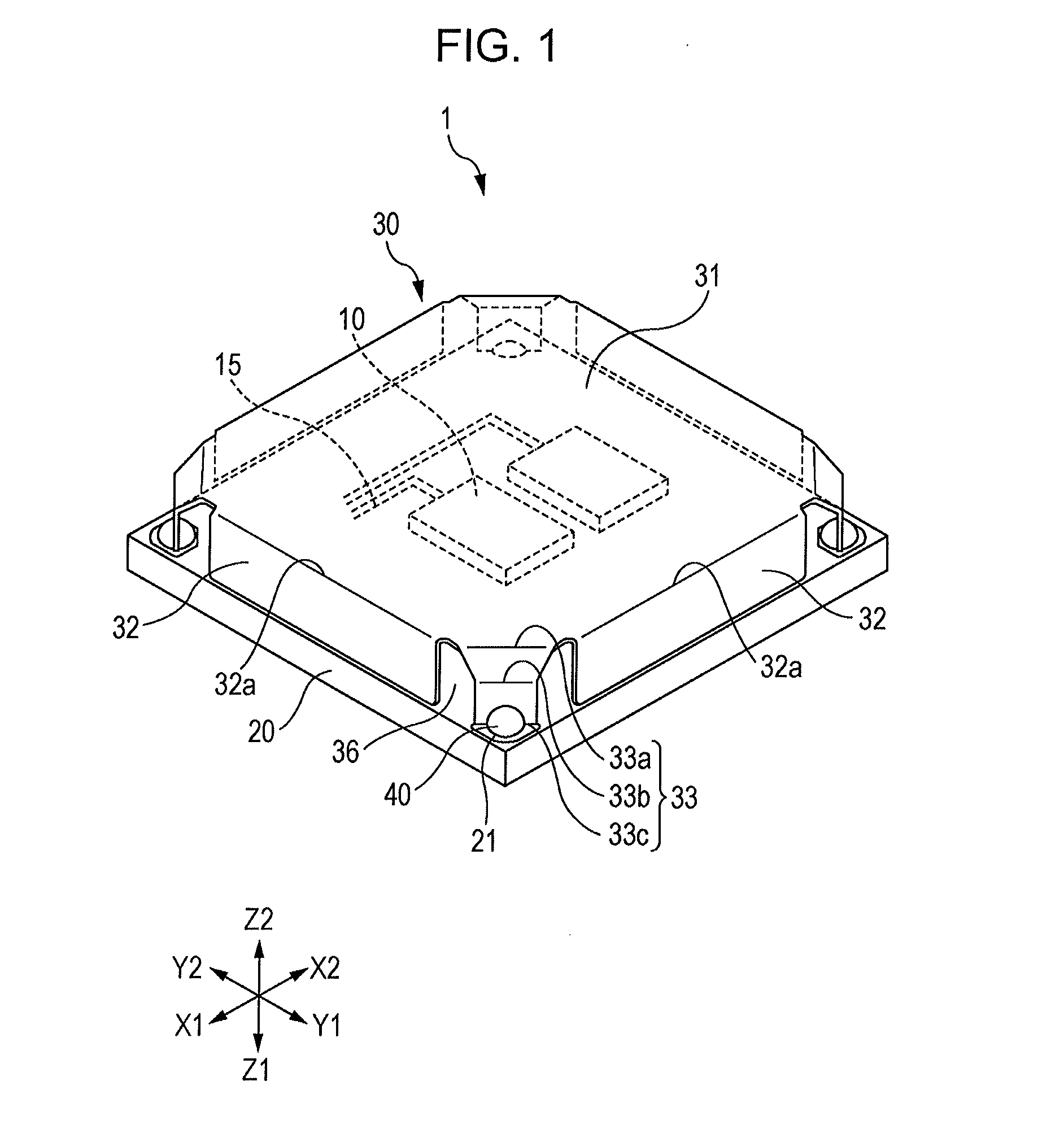
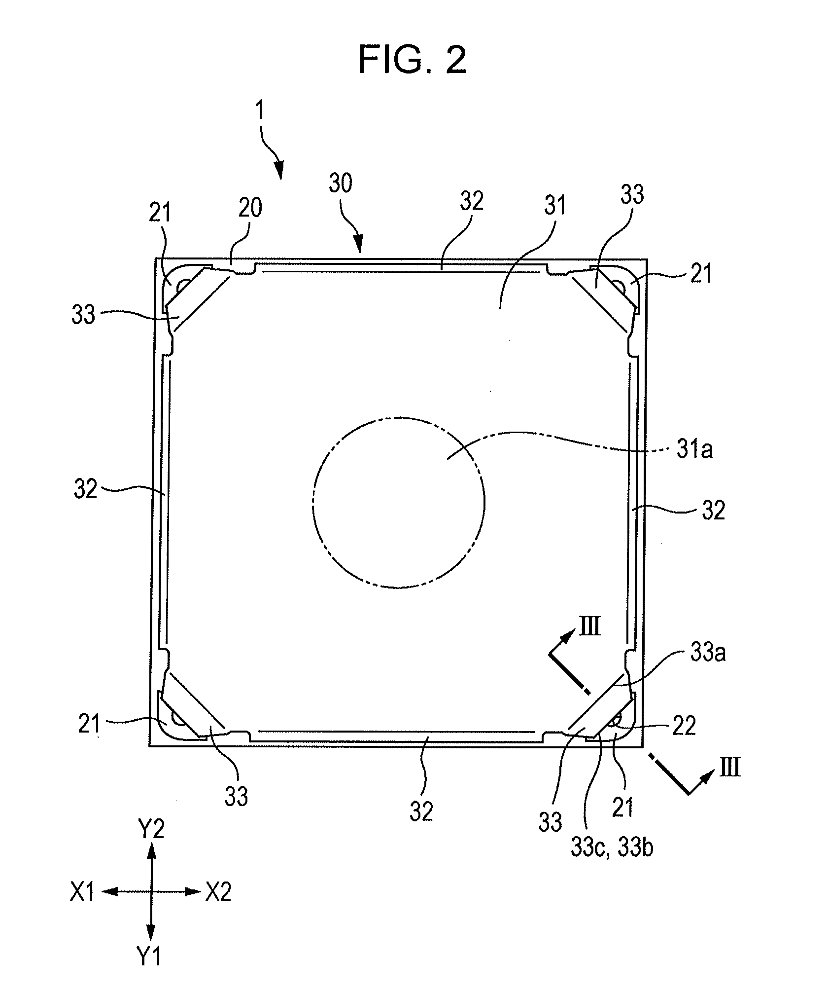
[0025]An electronic circuit module 1 in a first embodiment will be described below. FIG. 1 is a perspective view showing the electronic circuit module 1 of the first embodiment. FIG. 2 is a plan view of the electronic circuit module 1 seen from the top plate 31 side. FIG. 3 is a sectional view taken along line of FIG. 2. FIG. 4A is a semi-transparent plan view of the electronic circuit module 1 seen from the top plate 31 side, and FIG. 4B is a partial enlarged view. FIG. 5 is an enlarged view of a mounting leg 33 seen from the same direction as FIG. 1. FIG. 6 is a perspective view showing a first modification of the first embodiment. FIG. 7 is a perspective view showing a second modification of the first embodiment.

[0026]As shown in FIG. 1, a metal cover 30 is disposed so as to cover a circuit board 20. The metal cover 30 includes a top plate 31 that is substantially the same size as the planar size of the rectangular circuit board 20, a plurality of side plates 32 that are bent and...

second embodiment

[0049]FIG. 8 is a perspective view showing an electronic circuit module 2 of a second embodiment of the present invention. The electronic circuit module 2 differs from the electronic circuit module 1 of the first embodiment in that the side plates 32 each have a first side plate bent portion 32a bent from the top plate 31 of the metal cover 30, and a second side plate bent portion 32b located on the outer side of the first side plate bent portion 32a when seen from the upper surface of the circuit board 20. The components of the second embodiment are the same as those of the first embodiment, and the same reference numerals are used.

[0050]As shown in FIG. 8, the first side plate bent portion 32a is located closer to the center of the top plate 31 than the second side plate bent portion 32b. Although the height of the metal cover 30 is restricted by fixing the mounting legs 33 determining the distance between the circuit board 20 and the top plate 31, with solder 40, the side plates ...


PUM


Abstract

An electronic circuit module includes a circuit board on which electronic components are mounted, and a metal cover covering the circuit board. The metal cover includes a top plate disposed so as to face the circuit board, side plates, and mounting legs. The circuit board has lands to which the mounting legs are joined. The mounting legs each have a bent portion located on the outer periphery of the top plate of the metal cover, and a mounting leg fixing portion in contact with the lands of the circuit board. When seen from the upper surface of the circuit board, the position of the bent portion is on the inner side of the position of the mounting leg fixing portion, and the width of the bent portion is greater than the width of the mounting leg fixing portion.

Description

CLAIM OF PRIORITY[0001]This application claims benefit of Japanese Patent Application No. 2012-171370 filed on Aug. 1, 2012, which is hereby incorporated by reference in its entirety.BACKGROUND[0002]1. Field of the Disclosure[0003]The present disclosure relates to an electronic circuit module having a metal cover, and more specifically, it relates to an electronic circuit module in which deformation of a thin metal cover can be prevented.[0004]2. Description of the Related Art[0005]An electronic circuit module is a circuit module in which a high-frequency circuit or the like is formed by a circuit board on which electronic components are mounted. It is built in an electronic device and is used, for example, as an electronic circuit module forming a radio transceiver circuit. It is easy to mount a plurality of electronic circuit modules on a larger-scale circuit board (mother board).[0006]Examples of such an electronic circuit module include a high-frequency tuner module described in...

Claims


Application Information

Patent Timeline
IPC IPC(8): H05K9/00
CPCH05K9/0043H01L2924/0002H05K9/0028H01L2924/00H01L23/60H05K9/0009H05K9/0024H05K9/0026H05K9/0037H05K9/0049
Inventor WATANABE, YOSHIKIYO
Owner ALPS ALPINE CO LTD
Why Eureka
Try Eureka