Multi-cell battery

a multi-cell, battery technology, applied in the manufacture of secondary cells, cell components, cell component details, etc., can solve the problems of not being able to meet the needs of not being able to realistically compete with the new thin low cost batteries that are needed, and difficult or non-feasible to print power sources on circuits. to achieve the effect of convenient folding of flexible batteries

Active Publication Date: 2013-12-05
BLUE SPARK INNOVATIONS LLC
View PDF4 Cites 25 Cited by
  • Summary
  • Abstract
  • Description
  • Claims
  • Application Information

AI Technical Summary

Benefits of technology

[0010]In accordance with yet another aspect of the present application, a flexible battery is provided for generating an electrical current. A first substrate layer comprises a first cell portion, a second cell portion, and a bridge portion connecting the first and second cell portions. A first electrochemical cell is provided on the first cell portion, and a second electrochemical cell is provided on the second cell portion. An electrical bridge electrically couples the first electrochemical cell to the second electrochemical cell in series or parallel, wherein the electrical bridge is flexible and extends across the bridge portion of the first substrate layer. First and second liquid electrolytes are provided, respectively, in contact with the first and second electrochemical cells. A second substrate layer is connected to said first substrate layer to contain each of said first and second liquid electrolytes such that both of the first and second electrochemical cells are separately sealed. The flexible battery is configured to be folded over itself along the bridge portion such that the first and second electrochemical cells are arranged in a covering relationship. An open gap area is disposed between the first substrate layer and second substrate layer, and over the bridge portion of the first substrate, to thereby facilitate folding the flexible battery over itself along a line extending through the bridge portion.

Problems solved by technology

In the early days of portable power, these power sources were very large compared to today's standards.
This high cost battery with multiple layers and a metal foil laminate package is a high voltage, high current battery, capable of igniting flash bulbs and powering motors, for example, and is not a realistic competitor of the new thin low cost batteries that are needed.
However, there remain some other applications where economic considerations and / or technical or compatibility considerations make it difficult or non-feasible to print the power source on the circuit.

Method used


Image

  • Multi-cell battery
  • Multi-cell battery
  • Multi-cell battery

Examples


Embodiment Construction

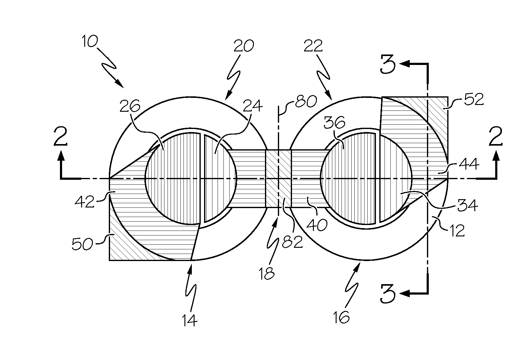
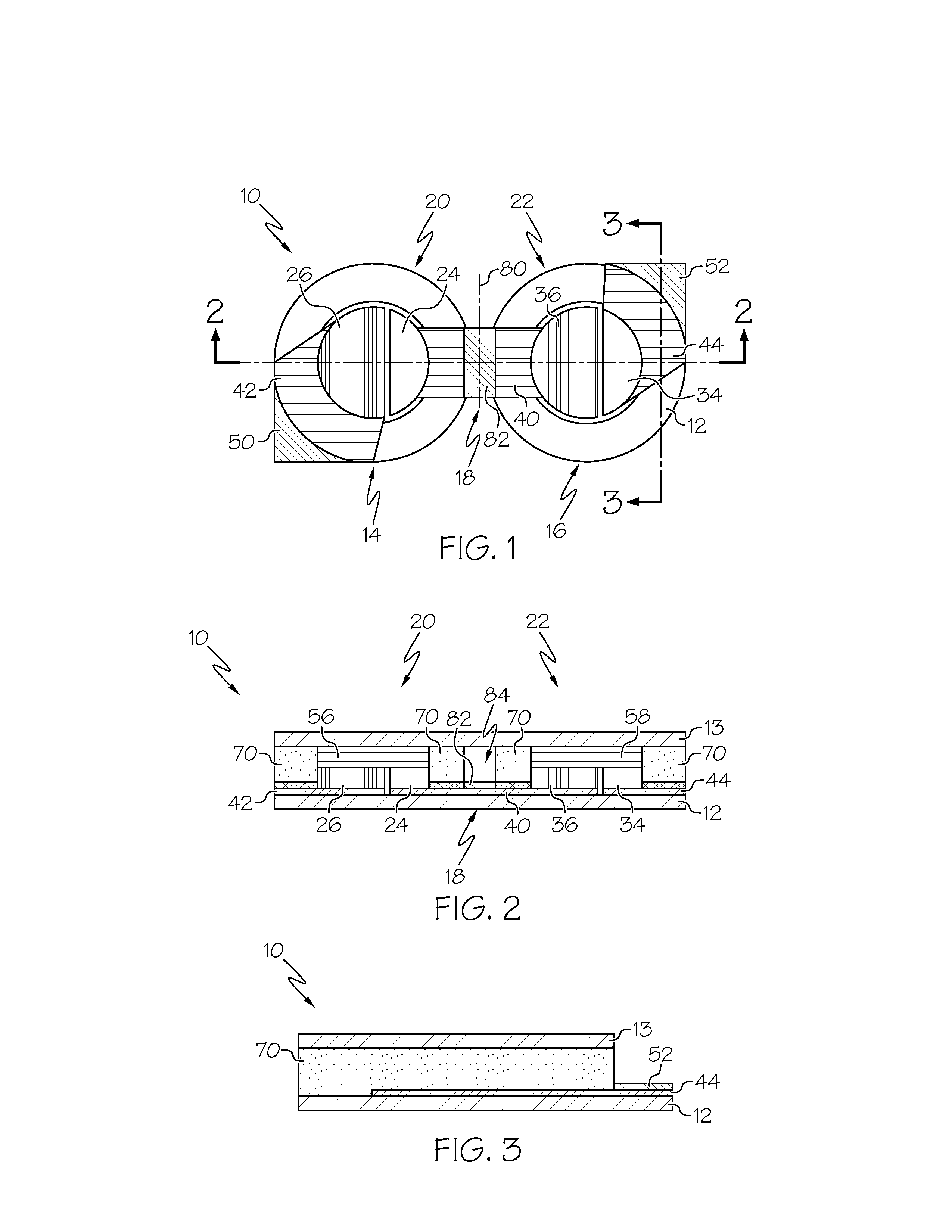
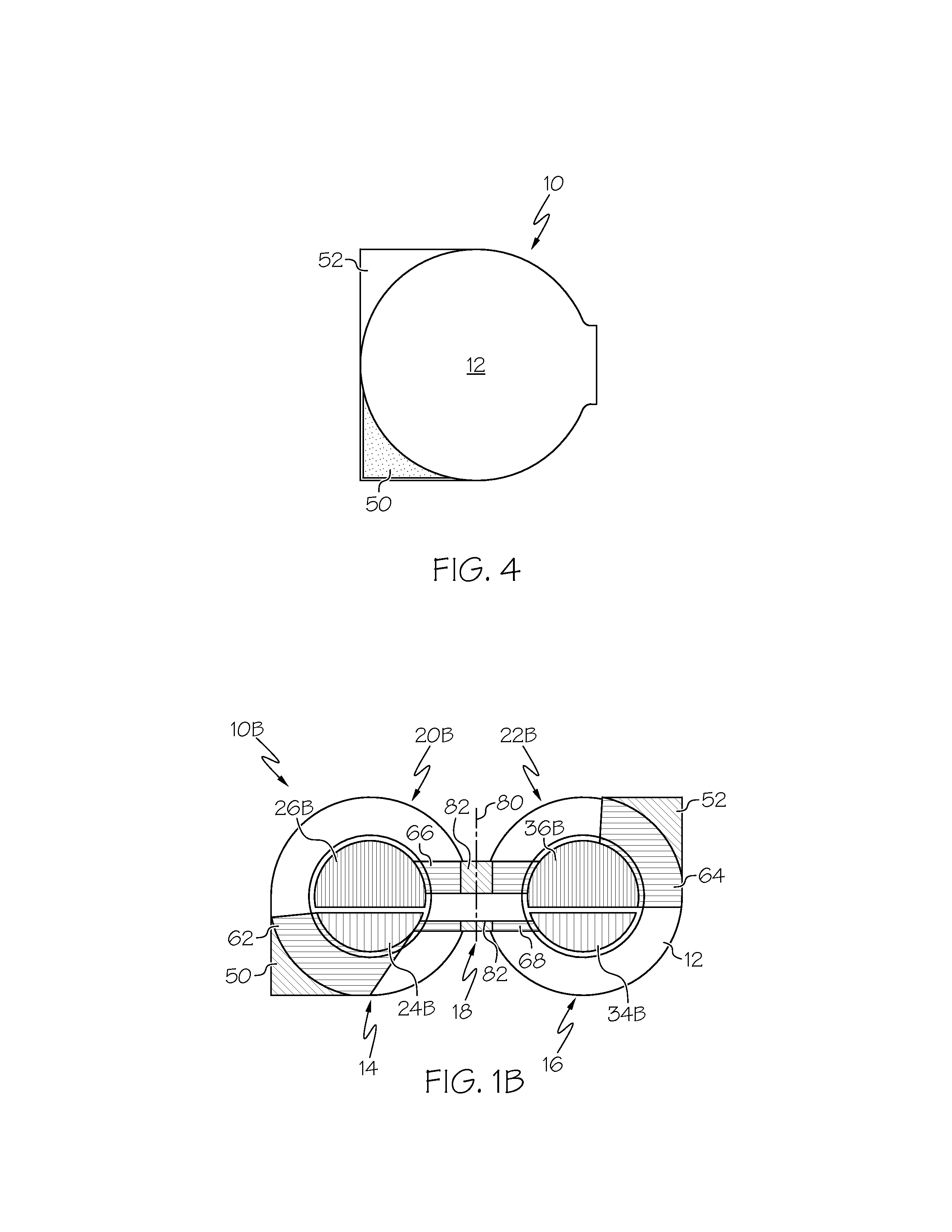
[0022]In the instant application, a flexible battery is provided for generating electrical current that comprises a plurality of electrochemical cells. Generally, some or all of the electrochemical cells are manufactured in the same overall operation. The flexible battery is folded over itself to provide a finished battery with multiple cells having a reduced surface area, such as substantially similar to that of battery with a single cell. For example, once the battery is completed, it is folded over itself about a fold-over line that can be located variously, such as about half-way along the length of the battery or at other locations. The top or bottom substrate, depending on which way the battery is folded, can include an exterior adhesive (e.g., PSA) such that when the battery is folded over itself it remains in a folded condition. Still, it is contemplated that the two (or more) cells could be used without folding, if desired.

[0023]Various methods can be used to manufacture fl...


PUM

PropertyMeasurementUnit
voltageaaaaaaaaaa
F.P.-freezing pointaaaaaaaaaa
freezing pointaaaaaaaaaa

Abstract

A flexible battery includes a first substrate layer with a first cell portion, a second cell portion, and a bridge portion connecting the first and second cell portions. An electrical bridge electrically couples a first electrochemical cell to a second electrochemical cell in series or parallel, and an electrical bridge is flexible and extends across the bridge portion of the first substrate layer. A second substrate layer is connected to the first substrate layer such that both of the first and second electrochemical cells are separately sealed. The flexible battery is configured to be folded over itself along the bridge portion such that the first and second electrochemical cells are arranged in a covering relationship. Optionally, an open gap area is disposed over the bridge portion of the first substrate to facilitate folding the flexible battery over itself along a line extending through the bridge portion.

Description

CROSS-REFERENCE TO RELATED APPLICATIONS[0001]This application claims the benefit of U.S. provisional application Ser. No. 61 / 649,455, filed on May 21, 2012, which is incorporated herein in its entirety by reference thereto.BACKGROUND OF THE INVENTION[0002]For the past one hundred years or so, scientists have been making Carbon / Zinc portable power sources for various applications. In the early days of portable power, these power sources were very large compared to today's standards. For example, the very popular “Igniter Cell” made by Eveready was about 3″ diameter and about 9″ tall and was used in many applications such as radios, buzzers, Xmas lighting, etc. These large cells, as well as some smaller versions, such as the famous Eveready #6 (about 2″ dia.×6″ tall) and the smallest unit cell of the day, the #950 (D size), were commonly made into battery packs with voltages exceeding 40 volts in some applications. These were similar in size, and even larger, than today's car batterie...

Claims


Application Information

Patent Timeline
Patent Type & Authority Applications(United States)
IPC IPC(8): H01M6/40H01M50/503H01M50/529H01M50/526
CPCH01M6/40H01M10/0427H01M10/285H01M10/365H01M6/42H01M12/085Y02E60/10H01M50/109H01M50/526H01M50/503
Inventor TUCHOLSKI, GARY R.
Owner BLUE SPARK INNOVATIONS LLC
Why Eureka
Try Eureka