Magnetic Connector

a technology of magnetic connectors and connectors, applied in the direction of coupling device connection, coupling/disconnecting parts, electrical equipment, etc., can solve the problems of severe damage to the connection system, inability to operate normally, and inability to connect normally

Inactive Publication Date: 2013-12-05
ADONIT
View PDF0 Cites 84 Cited by
  • Summary
  • Abstract
  • Description
  • Claims
  • Application Information

AI Technical Summary

Problems solved by technology

As a result, connections for such devices are more susceptible than usual to inadvertent disconnection, which may often be accompanied by excessive force, such as when a connecting cable is kicked or tripped on, or snags on an object.
Since most conventional connection systems employ some form of mechanical fixing means to maintain the integrity of the connection, such as pins, releases, or flexible members, such accidental disconnection presents a distinct threat of severe damage to the connection system, interrupting service and incurring replacement/repair costs.
This solution, however, involves a complex and costly connection for maintaining actual signal transmission.
The force of the magnet is sufficient to hold the load contacts in place for operation but insufficient to provoke damage to the connector plug or attached receptacle and any attached struct

Method used


Image

  • Magnetic Connector
  • Magnetic Connector
  • Magnetic Connector

Examples


Embodiment Construction

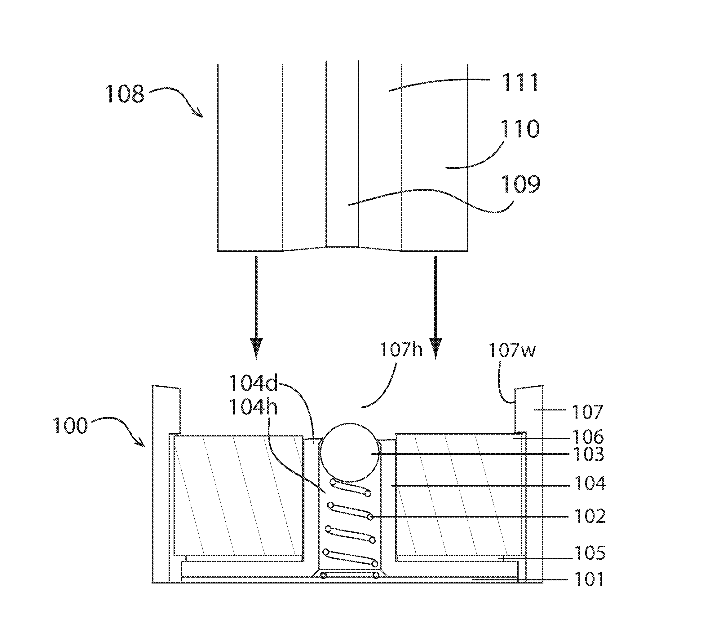
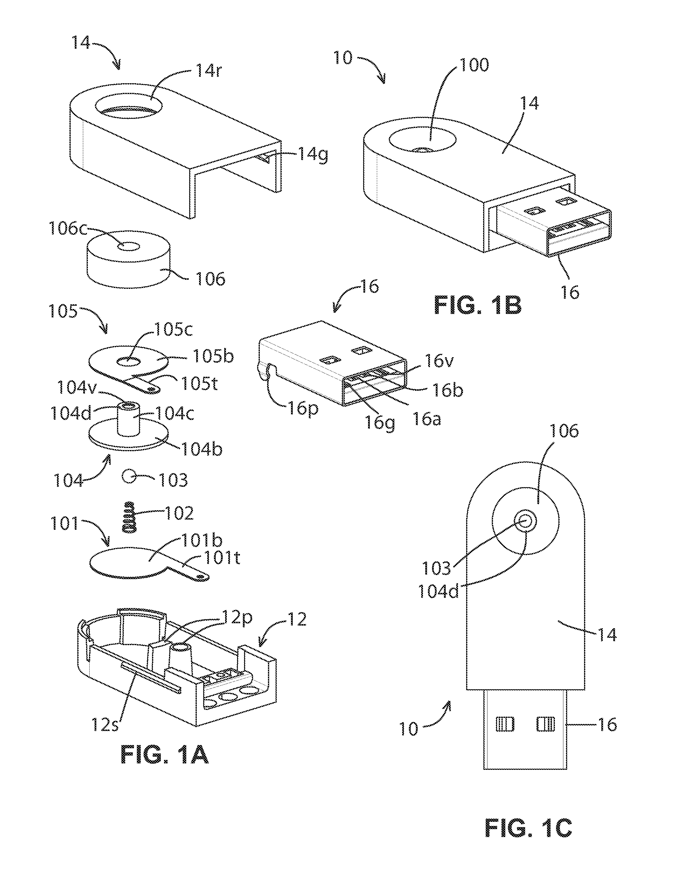
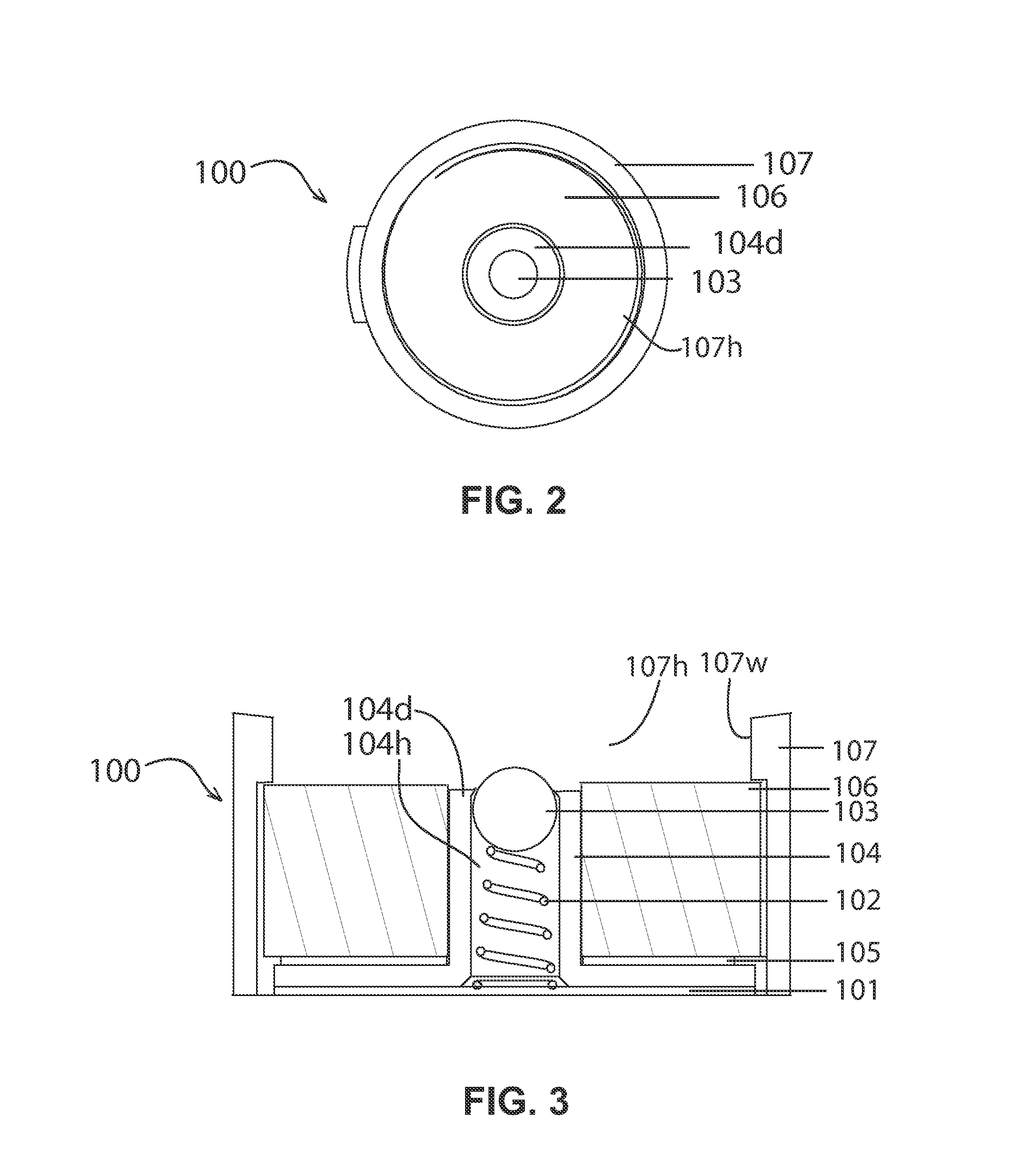
[0041]An electrical connector as disclosed may comprise at least a receiving side and a received side. In some embodiments, the receiving side may be deployed in a host, such as, for example, a panel or other PC, or in a dongle or other structure connecting to the host, and the received side may be deployed as part of a peripheral device or terminating a cable attached thereto. While descriptive details of the disclosure as follows are predicated on such an arrangement, alternative configurations, such as the received side deployed in the host and the receiving side on the peripheral device or cable attaching thereto, may be equally applicable and remain well within the scope of the disclosure.

[0042]FIG. 1A is an exploded diagram of a receiving side 100 of an embodiment of an electrical connector as disclosed, the receiving side 100 comprising a second terminal 101 having a body 101b and a trace 101t, a resilient member 102 seated thereon, and a contact member 103 seated at the end ...


PUM


Abstract

Embodiments of magnetic connectors are disclosed. Embodiments show the use of magnetic connectors for power and/or signal bus coupling to electronic devices from support bases, stands, or cables. In some embodiments, spherical contacts, such as ball bearings, are pressed into firm contact with an electronic device by the use of conductive springs, which in turn electrically couple the spherical contacts to the bus lines. Contact arrangements are shown which allow rotation of the electronic device against an embodiment of magnetic connector. Arrangements of multiple magnets having differing polarities are shown when alignment of an electronic device in a particular orientation is required.

Description

BACKGROUND[0001]1. Field of the Disclosure[0002]The disclosure relates to computer accessories, and more specifically, to a connector transmitting electrical signals and / or electrical power.[0003]2. Description of the Related Art[0004]With recent innovations, portable computing devices are experiencing a dramatic surge in popularity.[0005]The portability of the devices allows for deployment for use in a variety of external settings, such that peripheral devices may often be connected in environments unsuited to such installations. As a result, connections for such devices are more susceptible than usual to inadvertent disconnection, which may often be accompanied by excessive force, such as when a connecting cable is kicked or tripped on, or snags on an object. Since most conventional connection systems employ some form of mechanical fixing means to maintain the integrity of the connection, such as pins, releases, or flexible members, such accidental disconnection presents a distinc...

Claims


Application Information

Patent Timeline
IPC IPC(8): H01R13/62
CPCH01R13/6205H01R13/2478H01R11/30
Inventor ZELIFF, ZACHARY JOSEPHLI, YUEH HUAPERPICH, KRISTOPHERHUANG, YU TZULU, KAI YI
Owner ADONIT
Why Eureka
Try Eureka