Power Source Machinery

Inactive Publication Date: 2013-12-19
LI HEUNGTUNG +1
View PDF6 Cites 4 Cited by
  • Summary
  • Abstract
  • Description
  • Claims
  • Application Information

AI Technical Summary

Benefits of technology

The patent describes a power source machinery that uses a rotating part and a non-rotating part to generate electric energy. The rotating part includes a cylinder, rotating axle, and a whole ring connected in front, while the non-rotating part includes a rectangular reinforced concrete chamber, three air chambers with generators, and an axle ring. The generators are controlled to produce a quick cyclic flow and a slow cyclic flow, which are used to supply power to the city. The design of the non-rotating axle ring allows for smooth synchronization with the cylinder and ensures unobstructed flow channels during the quick cyclic flow. The two successful factors created by the slow and quick cyclic flows are efficient power utilization and sufficient time for the quick cyclic flow to be finished.

Problems solved by technology

When creating great wealth, harmful by-products are brought at the same time, which causes environment damage, wherein the environment damage is more and more serious as time goes on, and many disasters are caused by the environment damage.
However, there is an adverse tendency in reality: Many big financial groups want to make large fortune by grasping the economic fate, venality, and dominating the country.
They don't care about healthy of human beings, environment protection in the world, and the future of mankind.
With the rapid development of human population in later years, a large number of energy is required badly to support the society developing rapidly.
However, the new energy developed is more and more expensive, and the living standard of urban and rural citizen is hard to improve.
Although accidents in coal, oil, and nuclear industries cause environment pollutions and do harm to human's health for a long time, nowadays the development scale of nuclear energy is still increased gradually in many countries all over the world regardless of people's health and safety, which is not expected.
Although solar energy, wind energy, tidal energy, and combustible ice energy open new scientific ways, the green energy developed by investing large amounts of money is more and more expensive, and it is hard to improve the living standards of poor people to narrow the gap between the rich and the poor.

Method used


Image

  • Power Source Machinery
  • Power Source Machinery
  • Power Source Machinery

Examples


Embodiment Construction

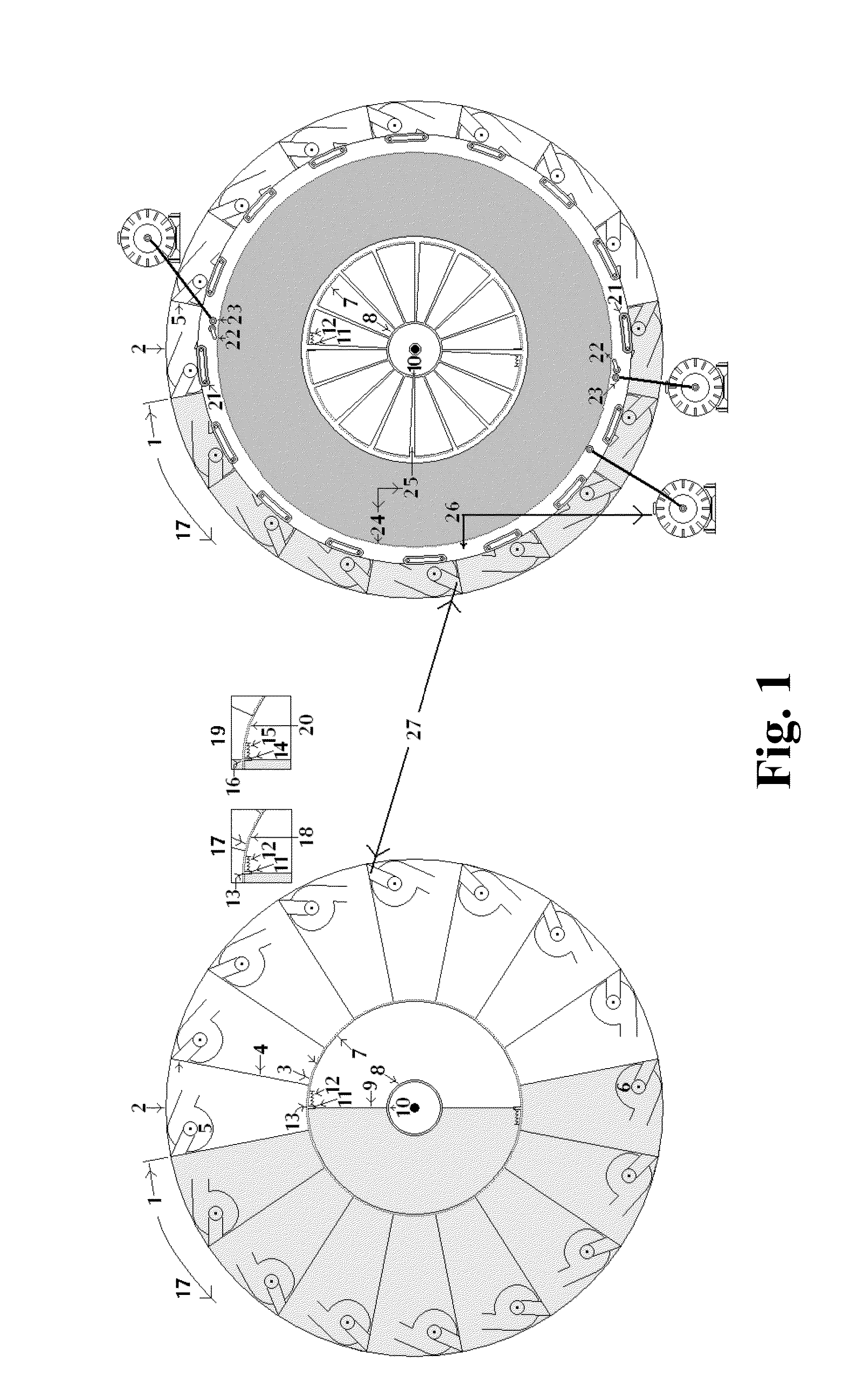
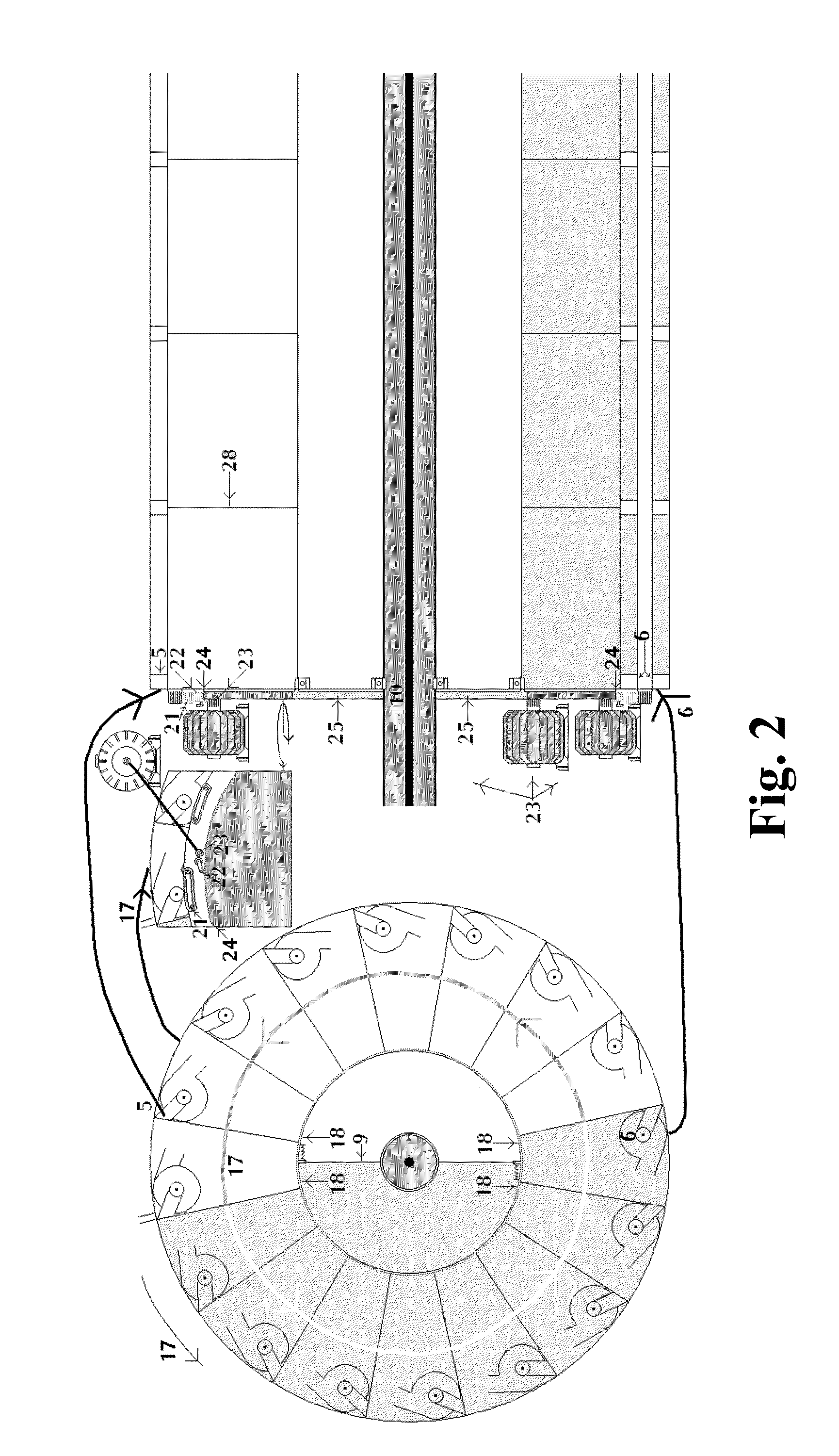
[0047]The present invention relates to a power source machinery, which is eco-friendly, operates under a room condition, does not pollute the environment, and can rotate and operate automatically without foreign energy inputted, wherein the power source machinery comprises three huge generators.

[0048]The present invention has three substances.

[0049]A first achievement of the present invention is as follows. The three huge generators are installed to drive the cylinder to rotate slowly, in such a manner that eco-friendly and cheap electricity is generated to benefit all mankind

[0050]A second achievement of the present invention is as follows. The cylinder uses ¼ of the power automatically and repeatedly. The quick cyclic flow is executed. The lever function of the liquid in the single water-caltrop-shaped element is improved, and an uninterruptible power source is created.

[0051]A third achievement of the present invention is as follows. The cylinder transfer 75% of the power to the t...


PUM


Abstract

The present invention is a power source machinery. The power source machinery has following functions. Firstly, a slow cyclic flow is generated in a first period, and a quick and slow cyclic flow is generated in a second period. Secondly, a first huge generator drives a cylinder to rotate slowly from beginning to end, and outputs a lot of electric energy. Thirdly, supply of rotary power to a second generator and a third generator is stopped, and the rotary power is transferred to a gas pump and a water pump, which are rotating to finish the quick cyclic flow. In every period, the quick flow raise liquid in a single water-caltrop-shaped element in a lower portion to a single water-caltrop-shaped element in a higher portion, which has a function of lever, in such a manner that the power source machinery rotates continuously for a long period.

Description

CROSS REFERENCE OF RELATED APPLICATION[0001]This is a U.S. National Stage under 35 U.S.0 371 of the International Application PCT / CN2011 / 083711, filed Dec. 08, 2011, which claims priority under 35 U.S.C. 119(a-d) to CN 201010579959.7, filed Dec. 08, 2010.BACKGROUND OF THE PRESENT INVENTION[0002]1. Field of Invention[0003]The present invention relates to a power source machinery, which is eco-friendly, operates under a room condition, does not pollute the environment, and can rotate and operate automatically without foreign energy inputted, wherein the power source machinery comprises three huge generators.[0004]2. Description of Related Arts[0005]Human intelligence develops rapidly since the 20th century. When creating great wealth, harmful by-products are brought at the same time, which causes environment damage, wherein the environment damage is more and more serious as time goes on, and many disasters are caused by the environment damage.[0006]Nowadays, many countries focus on th...

Claims


Application Information

Patent Timeline
IPC IPC(8): F03G7/00
CPCF03G7/00
Inventor LI, HEUNGTUNGLI, CHUNMAN
Owner LI HEUNGTUNG
Why Eureka
Try Eureka