Check patentability & draft patents in minutes with Patsnap Eureka AI!

Approach for supplying vacuum via a supercharger

a supercharger and vacuum technology, applied in the direction of non-positive displacement pumps, jet pumps, electric control, etc., can solve the problems of compressor surge, compressor stall/surge of turbocharger, compressor stall or stall reduction, etc., to reduce the effect of turbocharger stall/surge, reducing flow, and increasing the flow through the supercharger inl

Inactive Publication Date: 2013-12-19
FORD GLOBAL TECH LLC
View PDF28 Cites 43 Cited by
  • Summary
  • Abstract
  • Description
  • Claims
  • Application Information

AI Technical Summary

Benefits of technology

The patent describes a method to improve engine performance by using a supercharger to compress air before it reaches the turbocharger. This allows for better turbocharger operation and reduces the likelihood of stalling. The method also includes prioritizing the operation of the supercharger over the generation of vacuum for various uses during engine operation. Overall, the method ensures efficient and effective engine performance.

Problems solved by technology

However, the inventors herein have recognized potential issues with such an approach.
The typical pre-compressor throttle can either control engine load or control pre-compressor vacuum but it cannot do both with complete independence.
For example, throttling the compressor inlet of the turbocharger reduces flow circulation through the compressor that may result in a choke or stall.
Moreover, transient flow conditions created by adjustment of the throttle valve may cause compressor surge.
In either case, when such a condition occurs, drivability of the vehicle may be reduced and may be negatively perceived by a vehicle operator.

Method used


Image

  • Approach for supplying vacuum via a supercharger
  • Approach for supplying vacuum via a supercharger
  • Approach for supplying vacuum via a supercharger

Examples


Embodiment Construction

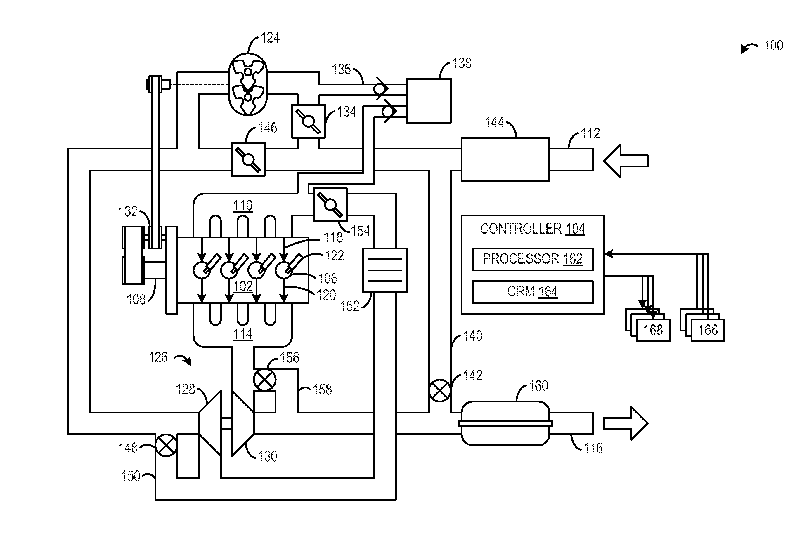
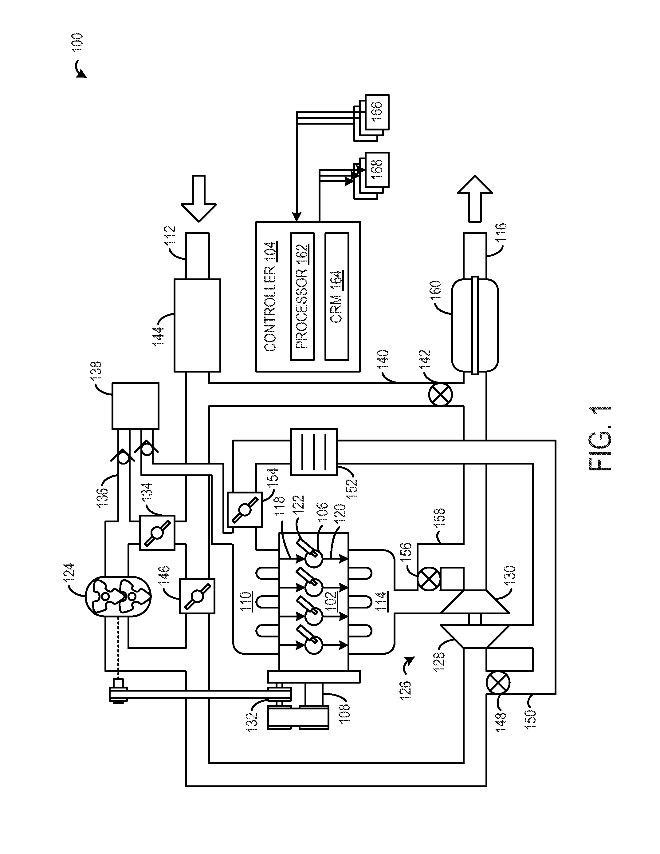
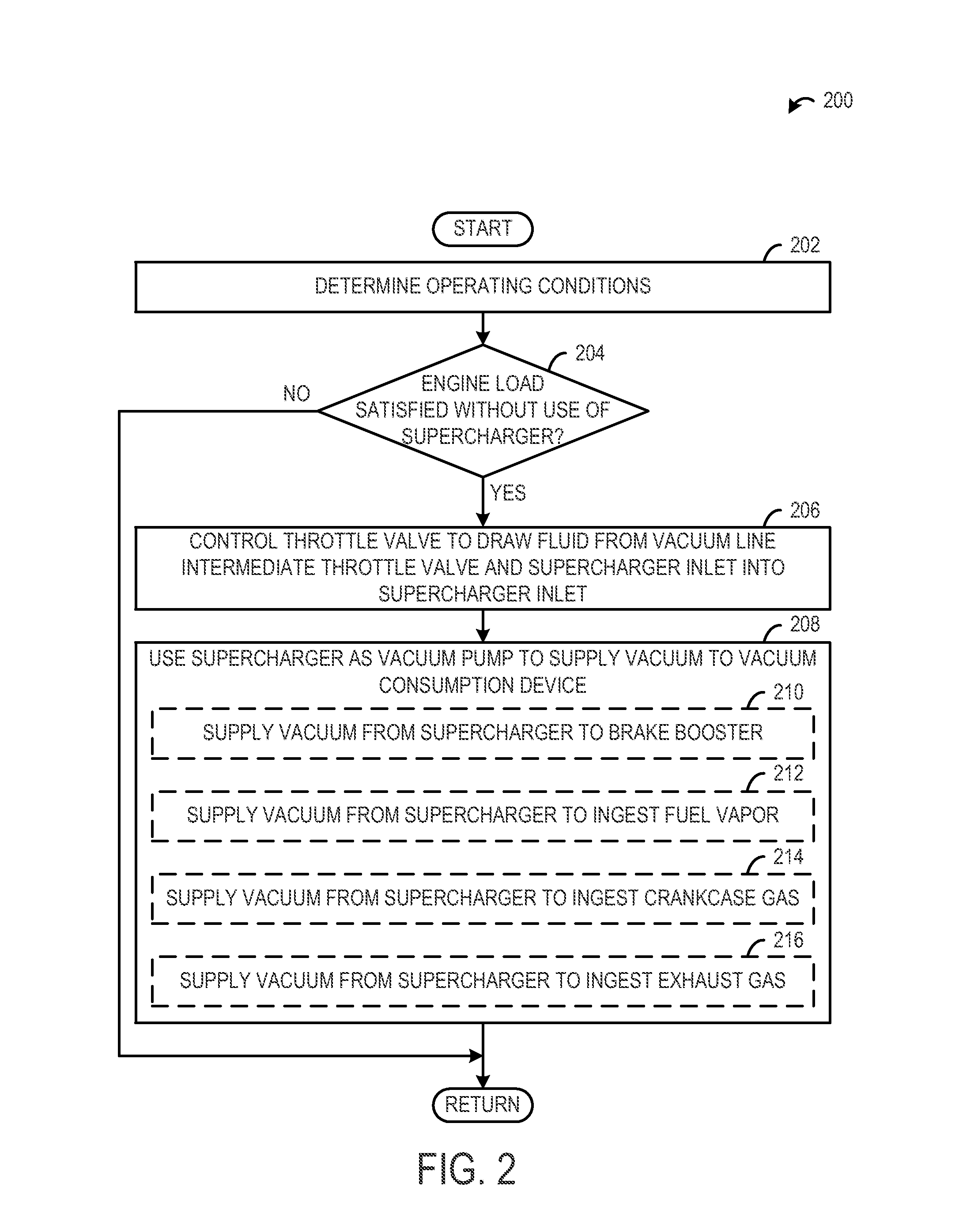
[0012]The present description relates to providing vacuum in an engine of a vehicle. More particularly, the present disclosure relates to an engine arrangement where a supercharger is positioned in series with and upstream of a turbocharger compressor in what may be referred to as a “twin charger” arrangement. For example, the supercharger may provide compression while the turbocharger spins up to operating speed in order to reduce or eliminate turbo lag. Once the turbocharger has reached operating speed, the supercharger can either continue compounding the pressurized air to the turbocharger inlet (yielding elevated intake pressures), or it can be bypassed and / or mechanically decoupled from the drive train via an electromagnetic clutch and bypass valve (increasing efficiency of the induction system). A throttle valve positioned upstream of the supercharger may be controlled to draw a fluid from a vacuum line positioned intermediate the throttle valve and a supercharger inlet to pro...


PUM


Abstract

A method for supplying vacuum in an engine is disclosed. The method includes controlling a throttle valve positioned upstream of a supercharger arranged in series with and upstream of a turbocharger to draw a fluid from a vacuum line positioned intermediate the throttle valve and a supercharger inlet.

Description

BACKGROUND AND SUMMARY[0001]Vacuum may be generated in an engine to create various actions that aid in operation of a vehicle. In one example, vacuum may be utilized to provide an actuating force for a device, such as for brake assist. In another example, vacuum may be utilized to circulate various fluids such as for exhaust gas recirculation (EGR), fuel vapor purge, crankcase venting, etc.[0002]In one example, a vehicle includes an engine having a throttle valve that is positioned upstream of a compressor inlet of a turbocharger. The throttle valve is operable to throttle fluid (e.g., intake air) entering the compressor inlet to generate vacuum. Such vacuum may be directed to operate an actuator or circulate other fluids during engine operation.[0003]However, the inventors herein have recognized potential issues with such an approach. The typical pre-compressor throttle can either control engine load or control pre-compressor vacuum but it cannot do both with complete independence....

Claims


Application Information

Patent Timeline
IPC IPC(8): F02D9/02F02B37/00
CPCF02B33/34F02B37/04F02B37/16F02B37/162F02B37/18F02B39/04F02B2037/125F02D23/00F02D41/0007F02D41/003F02D41/0065F02D41/021F02D2250/08F02D2250/41F04F5/20F04F5/52Y02T10/12F02B37/12F02D9/02
Inventor PURSIFULL, ROSS DYKSTRA
Owner FORD GLOBAL TECH LLC
Features
  • R&D
  • Intellectual Property
  • Life Sciences
  • Materials
  • Tech Scout
  • Unparalleled Data Quality
  • Higher Quality Content
  • 60% Fewer Hallucinations
Learn More