

Illuminating unit and inverted microscope
a technology of inverted microscope and illumination unit, which is applied in the field of illumination unit and inverted microscope, can solve the problems of reducing work efficiency and difficulty in improving the scalability of the system
- Summary
- Abstract
- Description
- Claims
- Application Information
AI Technical Summary
Benefits of technology
Problems solved by technology
Method used
Image

Examples
first embodiment
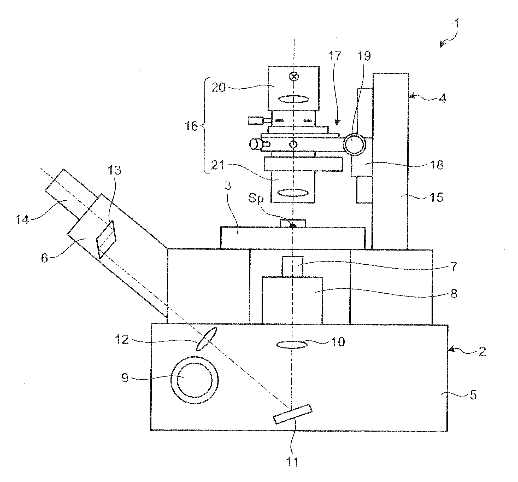
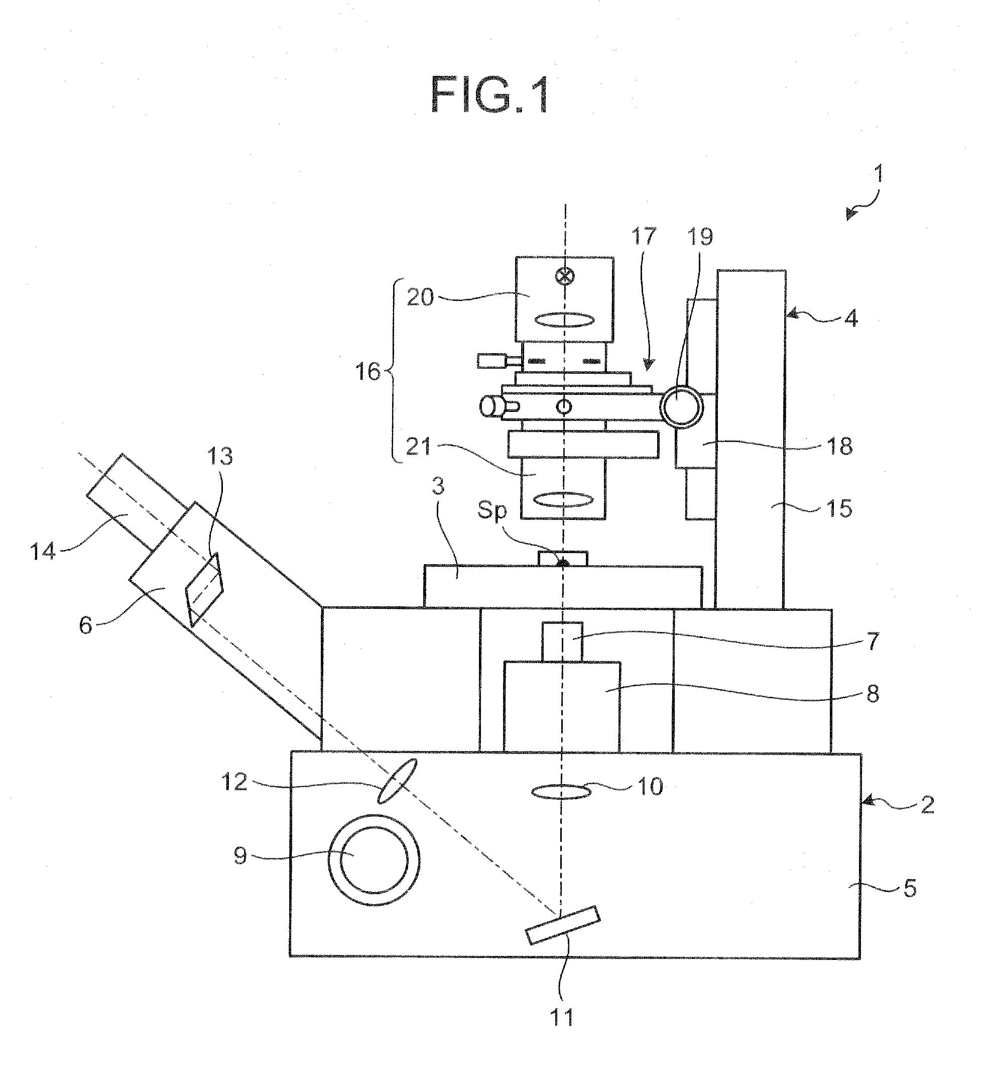
[0018]FIG. 1 is a diagram schematically illustrating an overall configuration of an inverted microscope according to a first embodiment of the present invention. An inverted microscope 1 illustrated in FIG. 1 includes a main body 2 serving as a base, a stage 3 that is mounted on a top surface of the main body 2 and that is used for placing a specimen Sp, and a transmitting illumination unit 4 that is located above the main body 2 and that applies transmitting illumination to the specimen Sp placed on the stage 3. The specimen Sp is held by a dish, a microscope slide, a beaker, or the like.
[0019]The main body 2 includes a casing 5 that supports the stage 3 and the transmitting illumination unit 4, and a lens barrel 6 that is provided on a front surface (left side surface in FIG. 1) that is a side surface facing a user of the inverted microscope 1 among the side surfaces of the casing 5.
[0020]The casing 5 includes a holder board 8 that holds an objective lens 7 in a replaceable manner...
second embodiment
[0039]FIG. 5 is a diagram illustrating configurations of an illuminating unit and a unit holder according to a second embodiment of the present invention and an overview of how the illuminating unit is assembled to the unit holder. An illuminating unit 41 illustrated in FIG. 5 includes a light source unit 42 and a condenser unit 43. The illuminating unit 41 is detachably attached to the unit holder 17 of the inverted microscope 1 described above. Therefore, the inverted microscope according to the second embodiment is configured similarly to the inverted microscope 1 by replacing the illuminating unit 16 with the illuminating unit 41.
[0040]The light source unit 42 includes the light source 22, the collector lens 23, the field stop 24, and the field-stop operating unit 25. A convex part 421 to be fitted to the condenser unit 43 is formed on a lower end portion of the light source unit 42. A male dovetail 422 in a shape that can be fitted to the female dovetail 291 of the U-shaped mem...
third embodiment
[0047]FIG. 6 is a diagram illustrating configurations of an illuminating unit and a unit holder according to a third embodiment of the present invention and an overview of how the illuminating unit is assembled to the unit holder. An illuminating unit 51 illustrated in FIG. 6 includes a light source unit 52, a field stop unit 53, and a condenser unit 54. The illuminating unit 51 is detachably attached to the unit holder 17 of the inverted microscope 1 as described above. Therefore, the inverted microscope according to the third embodiment is configured similarly to the inverted microscope 1 by replacing the illuminating unit 16 with the illuminating unit 51.
[0048]The light source unit 52 includes the light source 22 and the collector lens 22 A convex part 521 to be fitted to the field stop unit 53 is formed on a lower end portion of the light source unit 52.
[0049]The field stop unit. 53 includes the field stop 24 and the field operating unit 25. A concave part 531 that is be fitted ...
PUM
 Abstract
Description
Claims
Application Information