Frame unit, medium holding device and recording apparatus
- Summary
- Abstract
- Description
- Claims
- Application Information
AI Technical Summary
Benefits of technology
Problems solved by technology
Method used
Image

Examples
first embodiment (fig.1 through fig.5b)
First Embodiment (FIG. 1 Through FIG. 5B)
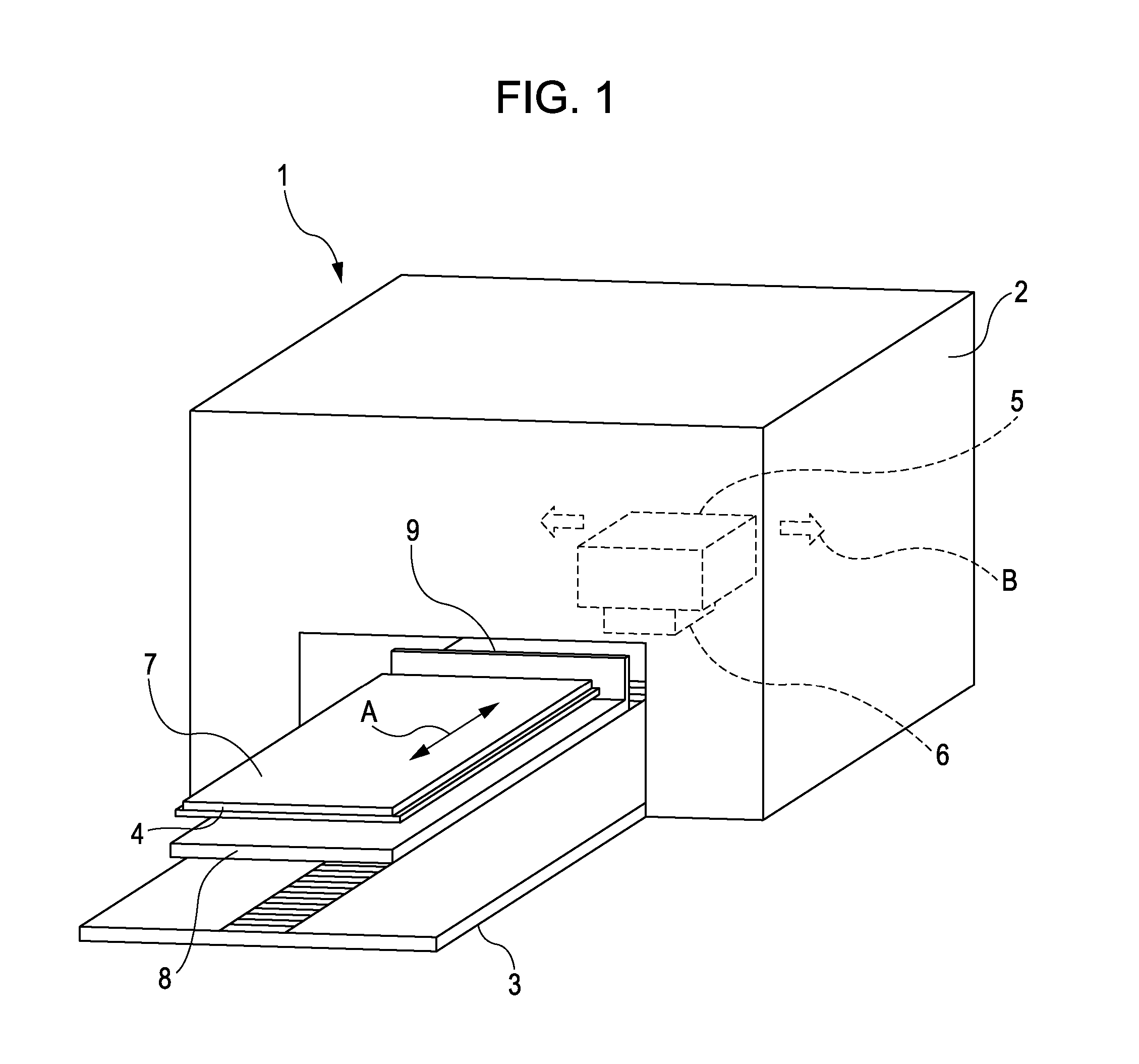
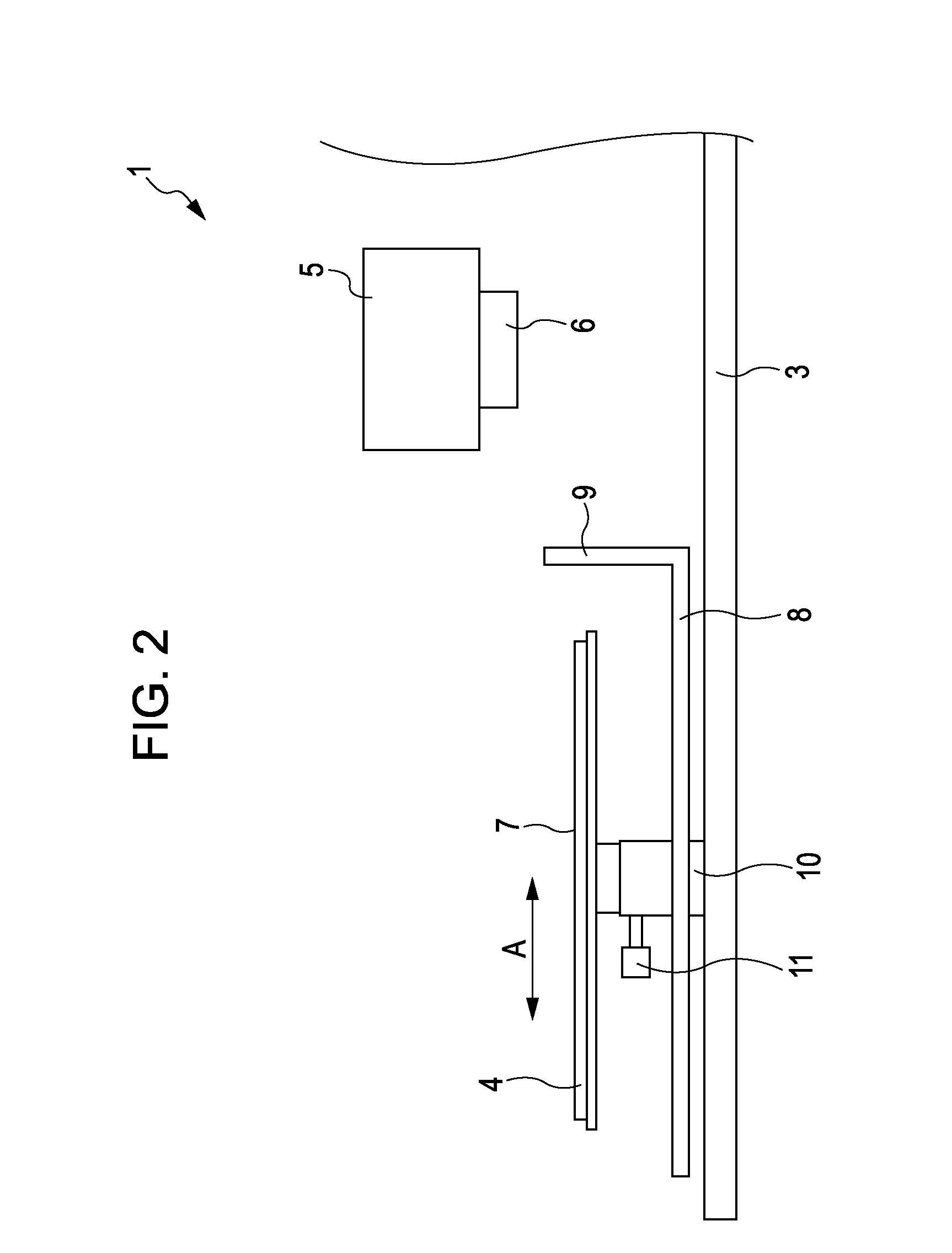
[0041]FIG. 1 is a schematic perspective view of a recording apparatus according to a first embodiment of the invention.
[0042]As shown in FIG. 1, a recording apparatus 1 according to this embodiment includes a tray 4 having a setting surface 7 on which a medium P (see FIGS. 3A and 3B) is set. A transport section 3 transports the medium P by moving the tray 4 in a transport direction A along the setting surface 7. A receiving tray 8 that can receive a part of the medium P sticking out from the setting surface 7 is provided under the tray 4. The receiving tray 8 is equipped with a plate member 9 to conceal the interior of the recording apparatus 1.
[0043]The tray 4 of this embodiment is detachable from the recording apparatus 1. Accordingly, a user can set the medium P in a state in which the tray 4 is detached from the recording apparatus 1. The user sets the medium P on the tray 4, which is detached from or attached to the recording apparatus 1...
second embodiment (
FIGS. 6A and 6B)
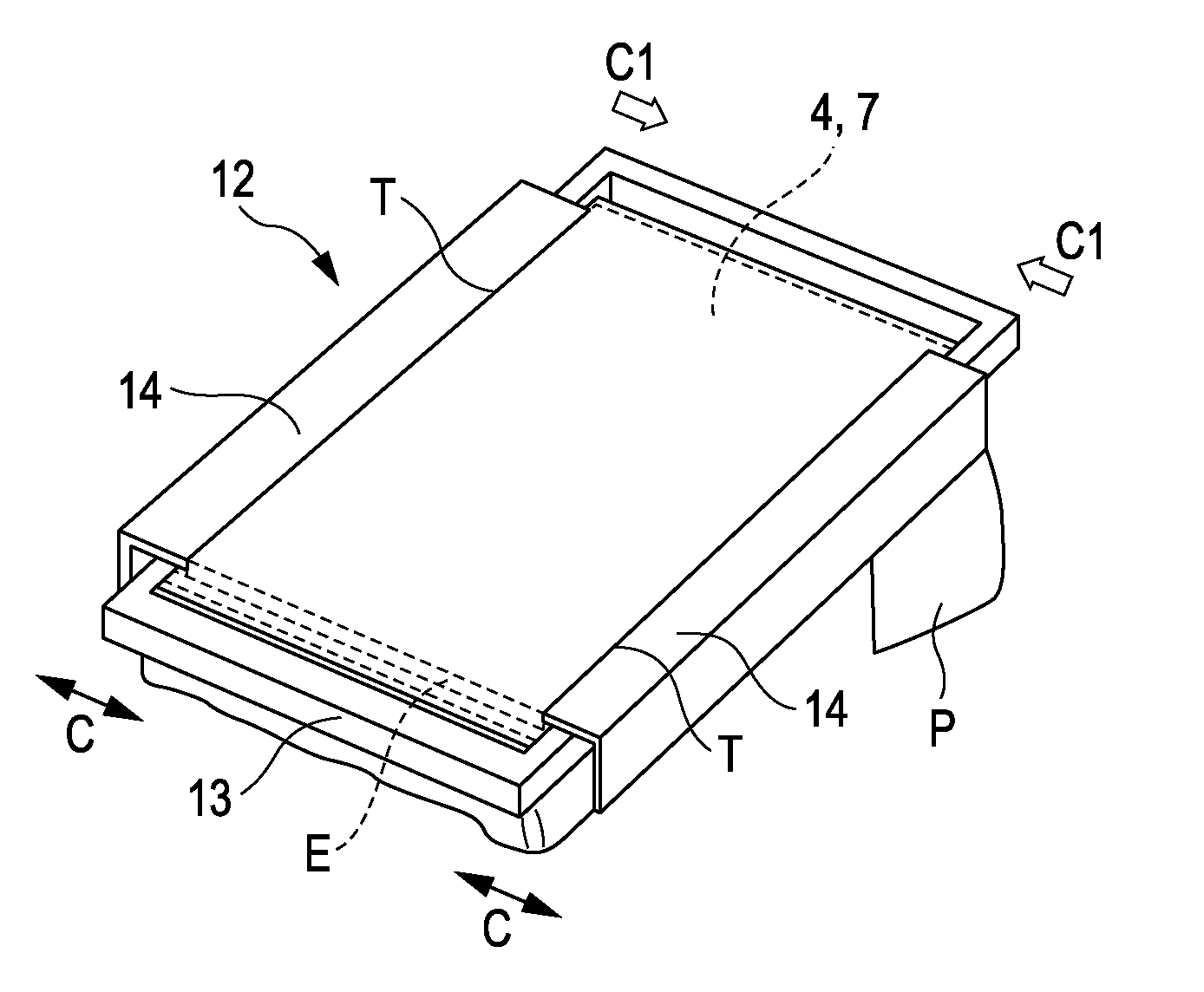
[0061]FIGS. 6A and 6B are enlarged schematic cross-sectional views illustrating a principal portion (frame unit 12) of a recording apparatus according to a second embodiment of the invention. Note that the same constituent members as those of the first embodiment are given the same reference numerals and detailed descriptions thereof are omitted.
[0062]In the frame unit 12 of this embodiment, a knob 17 is provided in the moving member 14 so that a user can move the moving member 14 in the inside-outside direction C with ease. The frame unit 12 of this embodiment has the same configuration as the frame unit 12 of the first embodiment except that the knob 17 is provided at the central portion in the lengthwise direction of the moving member 14.
[0063]The knob 17 of this embodiment is provided at the lower side of the moving member 14 and is formed in a plate shape extending in a depth direction of the drawing (direction vertical to the paper surface). However, the invent...
third embodiment (
FIGS. 7A and 7B)
[0064]FIGS. 7A and 7B are enlarged schematic cross-sectional views illustrating a principal portion (frame unit 12) of a recording apparatus according to a third embodiment of the invention. Note that the same constituent members as those of the first embodiment are given the same reference numerals and detailed descriptions thereof are omitted.
[0065]FIG. 7A is a schematic cross-sectional view illustrating a positional relationship between the tray 4 and the frame unit 12 before the frame unit 12 is fitted onto the tray 4 on which the medium P has been set. A user can fit the frame unit 12 onto the tray 4 by pressing the frame unit 12 in a lower-side direction F1 from a position thereof indicated in FIG. 7A with respect to the tray 4.
[0066]The leading edge T of the moving member 14 is tapered. In other words, a contact surface S of the moving member 14 to make contact with the medium P when the base frame 13 is fitted is inclined with respect to the setting surface 7...
PUM
 Abstract
Description
Claims
Application Information