
Valve apparatus

Inactive Publication Date: 2013-12-26
HP WELLHEAD SOLUTIONS
View PDF9 Cites 24 Cited by
  • Summary
  • Abstract
  • Description
  • Claims
  • Application Information

AI Technical Summary

Benefits of technology

This patent is for a valve apparatus for a well. The apparatus includes a valve body and a valve member. The valve body has a first passage and a second passage that extends laterally from the first passage. The valve member is inserted into the first passage and can control the flow of fluid from the first passage into each second passage. The valve apparatus also includes a threaded shank, a rod, a flange, and a seal. The valve member cap is rotatable and can sealingly engage the valve member and the valve seat to prevent fluid from flowing past the valve seat. The valve member also has a diffuser that can protect the valve body and the valve member from wear. The technical effect of this patent is to provide a reliable and durable valve apparatus for controlling fluid flow in a well.

Problems solved by technology

A blowout in the context of well drilling is the uncontrolled release of crude oil and / or natural gas from an oil well or gas well after pressure control systems have failed.
There have recently been a number of oil well blowouts.
Another blowout which resulted in the destruction and sinking of the Deepwater Horizon oil rig occurred in the Gulf of Mexico on 20 Apr. 2010.
Both the Timor Sea blowout and the Gulf of Mexico blowout resulted in the uncontrolled release of large quantities of crude oil and natural gas into the surrounding environment.
The release of this crude oil and natural gas has been quite harmful to the surrounding environments as well as to the wildlife inhabiting those environments.
Although blowout preventers are intended to be fail-safe devices, they nevertheless do occasionally fail.
If a blowout preventer fails, it can be very difficult to regain control over the flow of oil and / or gas from the well.
During the period that control is lost, a large quantity of oil and / or gas from the well may flow into the surrounding environment.
Even if a blowout preventer successfully prevents a blowout from occurring, the sudden increase in pressure in the well that is caused by the operation of the blowout preventer can damage the well and also the geological formation in which the well has been drilled.
In some cases, the damage to the well and the formation can be severe enough that oil and / or gas is / are able to escape from the well and flow into the formation.

Method used


Image

  • Valve apparatus
  • Valve apparatus
  • Valve apparatus

Examples


Embodiment Construction

[0114]In the drawings, like features of the various preferred embodiments have been referenced with like reference numbers.

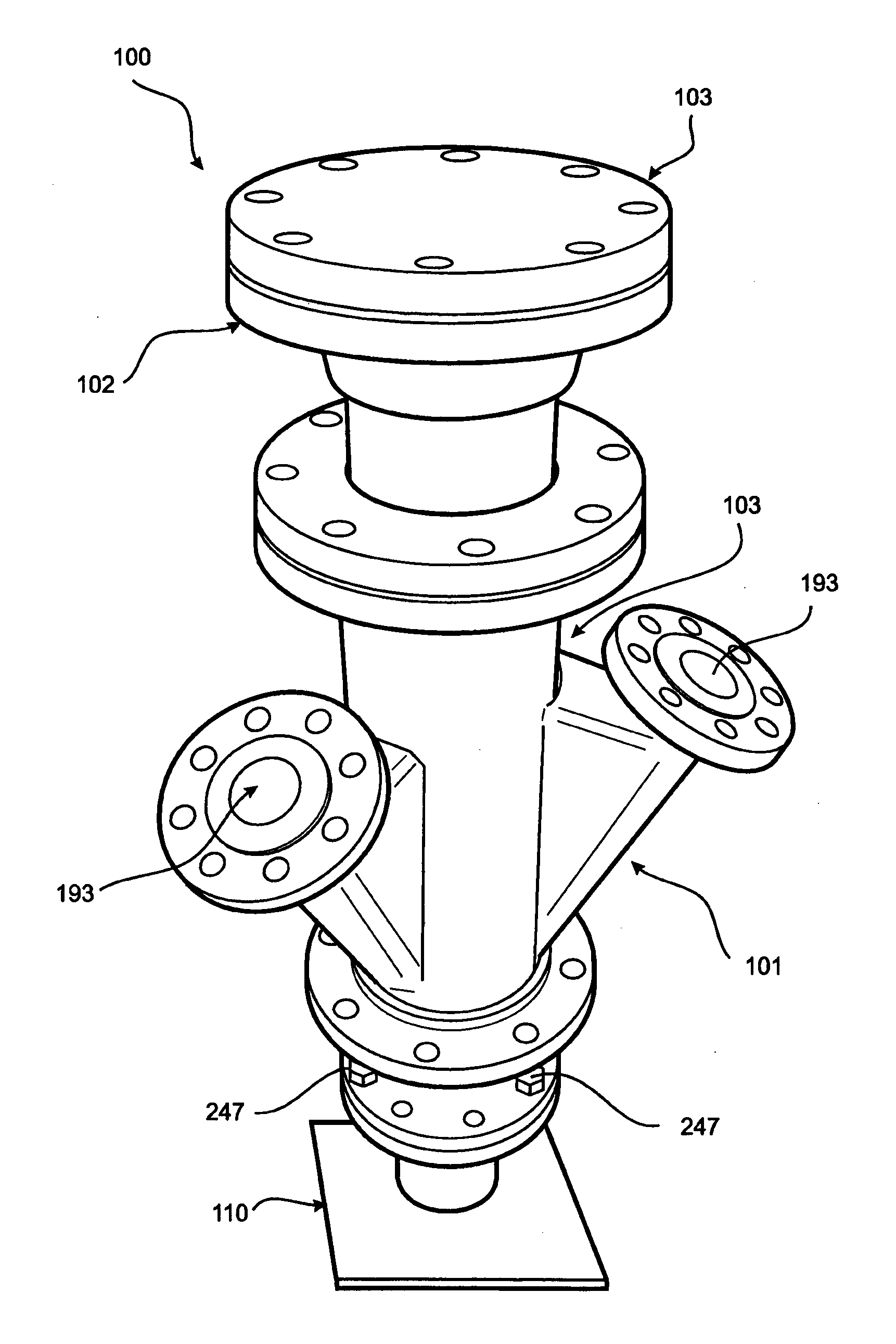
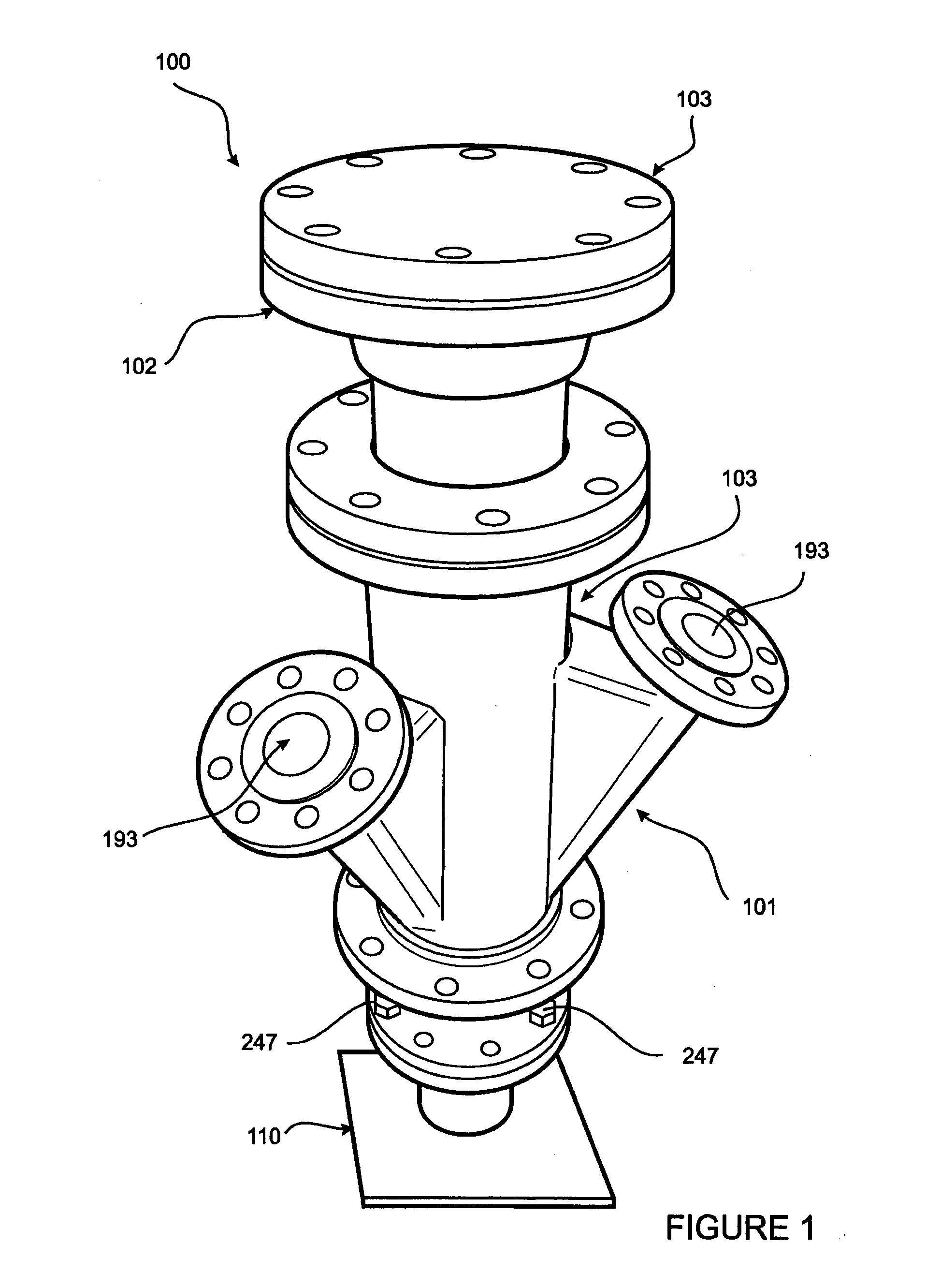
[0115]Referring to FIG. 1, a first preferred embodiment of a valve apparatus 100 for controlling the flow of oil or gas from a well such as, for example, a subsea well, includes a valve body 101, a valve member 102, and a valve member cap 103. The valve 100 is shown mounted on a mock-up of a flanged pipe outlet 104.

[0116]The valve body 101, valve member 102, and the cap 103 each comprise a plurality of separate parts that are secured together. In other preferred embodiments, the valve body 101, valve member 102, or the cap 103 may be formed as a single piece. For example, the valve body 101, valve member 102, or the cap 103 may be cast as a single piece.

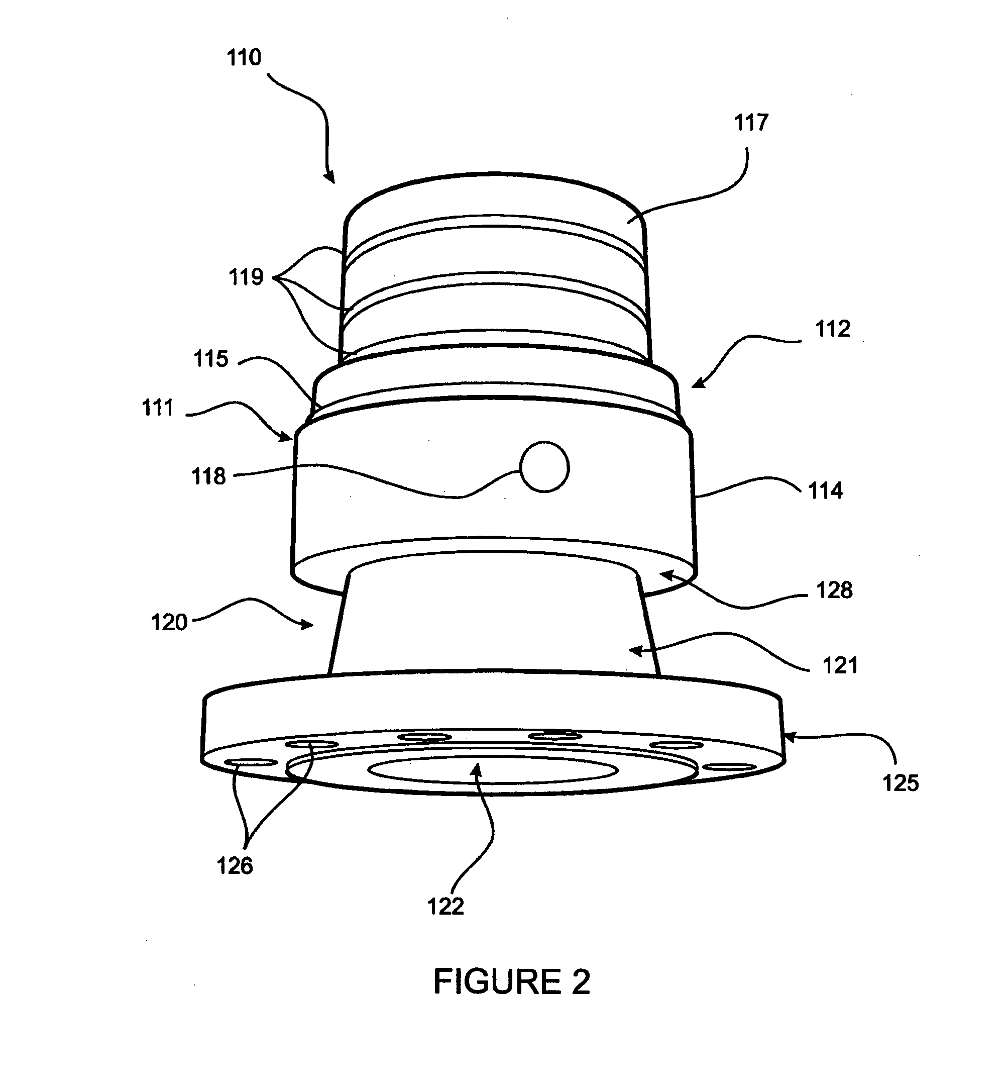
[0117]Referring to FIG. 2, the valve body 101 includes a first part 110. The first part 110 includes a pipe 111. A wall 112 of the pipe 111 defines a bore 113 (see FIG. 4) of the pipe 111. Wall 112 includes a fir...


PUM


Abstract

A valve apparatus (100) for a well comprises a valve body (101), and a valve member (102). The valve body (101) includes a first passage (190) that extends through the valve body (101), and at least one second passage (193) that extends through the valve body and laterally from the first passage (190). The valve body (101) being connectable to the well so that a fluid flowing from the well is able to flow through the first passage (190). The valve member (102) being insertable into the first passage (190) and being moveable relative to the valve body (101) so as to thereby control the flow of the fluid from the first passage (190) into each second passage (193).

Description

FIELD OF THE INVENTION[0001]The present invention relates generally to valve apparatus for controlling the flow of a fluid from a well.[0002]Although the present invention will be described with particular reference to being used to control the flow of crude oil and / or natural gas from a well, it will be appreciated that it is not necessarily limited to this particular use.BACKGROUND ART[0003]A blowout in the context of well drilling is the uncontrolled release of crude oil and / or natural gas from an oil well or gas well after pressure control systems have failed.[0004]There have recently been a number of oil well blowouts. On 21 Aug. 2009 the West Atlas oil rig was involved in a blowout that occurred in the Timor Sea off the coast of Western Australia. Another blowout which resulted in the destruction and sinking of the Deepwater Horizon oil rig occurred in the Gulf of Mexico on 20 Apr. 2010.[0005]Both the Timor Sea blowout and the Gulf of Mexico blowout resulted in the uncontrolle...

Claims


Application Information

Patent Timeline
IPC IPC(8): E21B33/06F16K11/06E21B34/14
CPCE21B33/063E21B34/14F16K11/06E21B29/08E21B33/035E21B34/04E21B43/0122Y10T137/8782E21B34/025
Inventor HUGHES, JIMPARKER, DALE
Owner HP WELLHEAD SOLUTIONS
Learn More