Fault tolerant parallel receiver interface with receiver redundancy

a parallel receiver and redundancy technology, applied in the field of high-speed communication interfaces, can solve the problems of low hardware overhead, link susceptible to temperature drift, and higher power consumption, and achieve the effect of avoiding 100% overhead and avoiding transmitting and lane overhead

Inactive Publication Date: 2013-12-26
IBM CORP
View PDF5 Cites 4 Cited by
  • Summary
  • Abstract
  • Description
  • Claims
  • Application Information

AI Technical Summary

Benefits of technology

[0005]It would be highly desirable to employ bus-level redundancy only within the receiver of a parallel interface to permit periodic recalibration of all receivers in the presence of a faulty transmission channel. This avoids the 100% overhead associated with bit-receiver level redundancy. Moreover, it avoids the transmit and lane overhead at the bus level associated with lane redundancy.

Problems solved by technology

It is common for receivers to be calibrated (i.e., determine sampling clock phase, equalizer coefficients, offset settings, etc) at startup; however, failure to recalibrate during normal receiver operation makes the links susceptible to temperature drifts.
This level of redundancy results in at least 100% hardware overhead.
Either approach results in higher power consumption due to the extra circuitry involved.
Moreover, protocol overhead is required to schedule which lane is being recalibrated, and which of the N lanes contain information about the data that is being communicated.

Method used


Image

  • Fault tolerant parallel receiver interface with receiver redundancy
  • Fault tolerant parallel receiver interface with receiver redundancy
  • Fault tolerant parallel receiver interface with receiver redundancy

Examples


Embodiment Construction

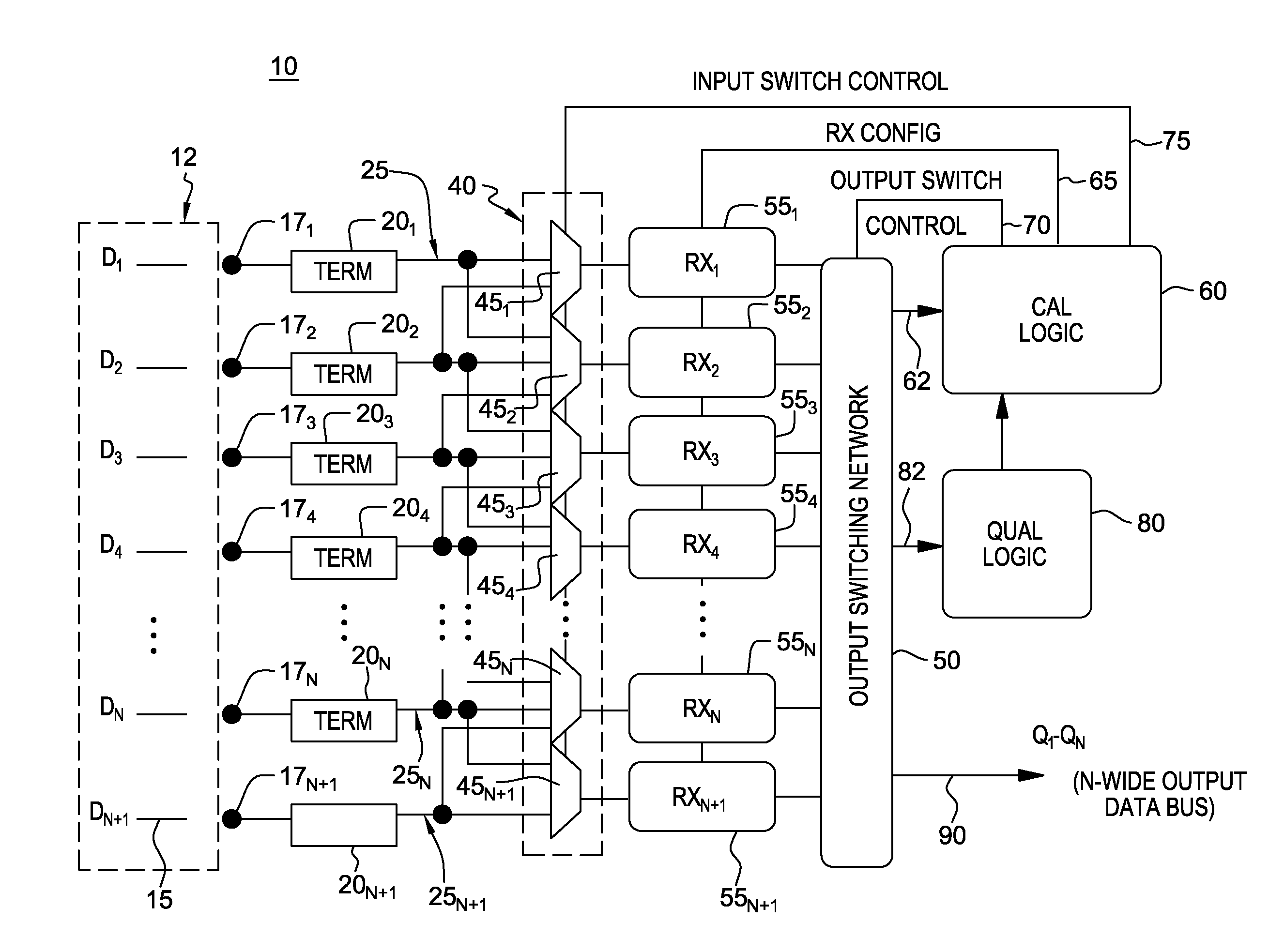
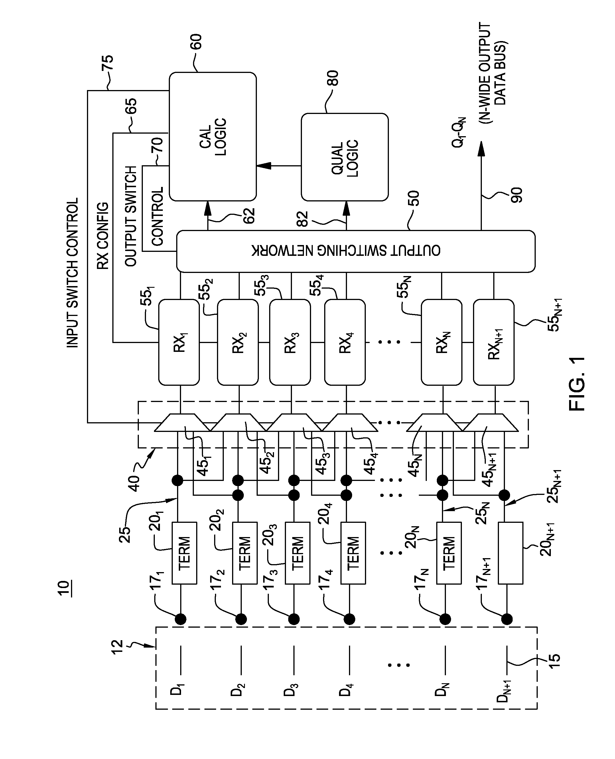
[0018]Commonly-owned co-pending U.S. Patent Application No. 61 / 664,266 describes a parallel receiver interface with receiver redundancy (“receiver shadowing”) and a method for implementing receiver calibration with no bandwidth reduction by permitting periodic recalibration (e.g., in a round-robin fashion) of N+1 bit receivers processing N input bits. This was accomplished by routing any given input pin to two (2) receivers such that one receiver could be calibrated, while the other receiver was processing the data and providing qualifications to the calibration process as needed.

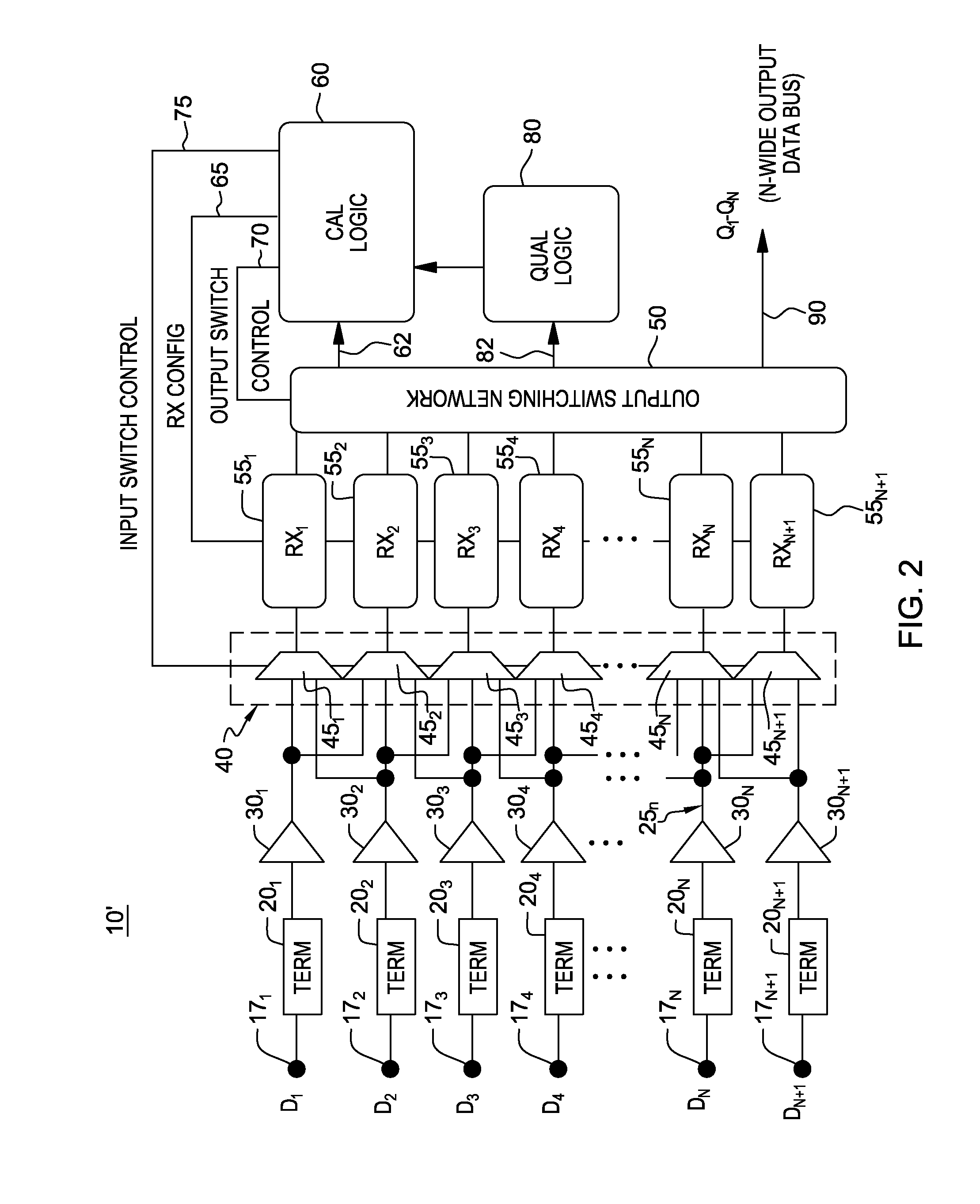
[0019]The present disclosure enhances the receiver shadowing architecture by adding additional structure to permit the inclusion of a data spare in the bus, and consequently, is tolerant to packaging or other faults such as an open circuit in the data channel between transmitter and receiver.

[0020]Particularly, a modified fault-tolerant receiver shadowing architecture still uses N+1 receivers to process N i...


PUM


Abstract

A communications parallel bus receiver interface having N+1 data lines and method of operation. The parallel bus interface employs receiver redundancy at the bus level such that there are N+1 receiver devices. One of the N+1 data signals comprising a spare data signal when a failure occurs in a corresponding channel transmitting one of N parallel data signals. An input switching network is configured to receive and couple N+1 parallel data signals along respective paths to corresponding parallel-configured bit receiver devices, and adapted to couple one received data signal to two or three adjacent bit receivers. A calibration device calibrates one of the two or three adjacent bit receivers, and a qualification device qualifies data decisions made during calibration processes performed by the calibration device. The method cycles through N+1 receivers for periodic recalibration of each receiver (one at a time) while N+1 inputs are processed continuously and uninterrupted.

Description

RELATED APPLICATIONS[0001]The present application relates to and claims the benefit of the filing dates of U.S. provisional application Ser. No. 61 / 664,266 filed Jun. 26, 2012 and 61 / 675,148 filed Jul. 24, 2012, both of which are incorporated herein by reference.GOVERNMENT CONTRACT[0002]This invention was made with Government support under Contract No.: H98230-07-C-0409 (awarded by National Security Agency (NSA)). The Government has certain rights in this invention.FIELD[0003]The present disclosure generally relates high-speed communication interfaces, such as high-speed parallel bus interface for integrated circuits, and more particularly to a fault-tolerant implementation of receiver redundancy within a parallel receiver interface to enable calibrations of all receivers in the parallel interface without interrupting data processing.BACKGROUND[0004]High-speed serial I / O is a critical part of computing systems. In server applications where I / O number in the thousands, achieving low-...

Claims


Application Information

Patent Timeline
Patent Type & Authority Applications(United States)
IPC IPC(8): H04L12/24
CPCH04L41/00G06F11/2007H04L49/113H04L49/10G06F13/00
Inventor DICKSON, TIMOTHY O.DREPS, DANIEL M.FERRAIOLO, FRANK D.
Owner IBM CORP
Why Eureka
Try Eureka