System and method for generating image window view settings

a technology of image window and setting, applied in the field of imaging systems, can solve the problems of increasing the time required by the user to perform a diagnosis of the patient, and inexperienced users may not have the knowledge to properly adjust the various parameters

Active Publication Date: 2013-12-26
GENERAL ELECTRIC CO
View PDF3 Cites 11 Cited by
  • Summary
  • Abstract
  • Description
  • Claims
  • Application Information

AI Technical Summary

Problems solved by technology

Accordingly, the manual features on the conventional imaging system are time consuming to operate and may therefore increase the time required by the user to perform a diag

Method used


Image

  • System and method for generating image window view settings
  • System and method for generating image window view settings
  • System and method for generating image window view settings

Examples


Embodiment Construction

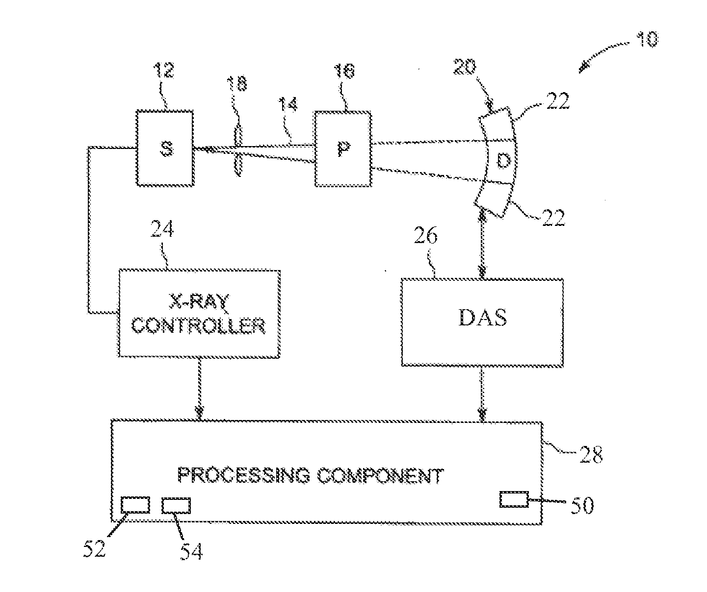
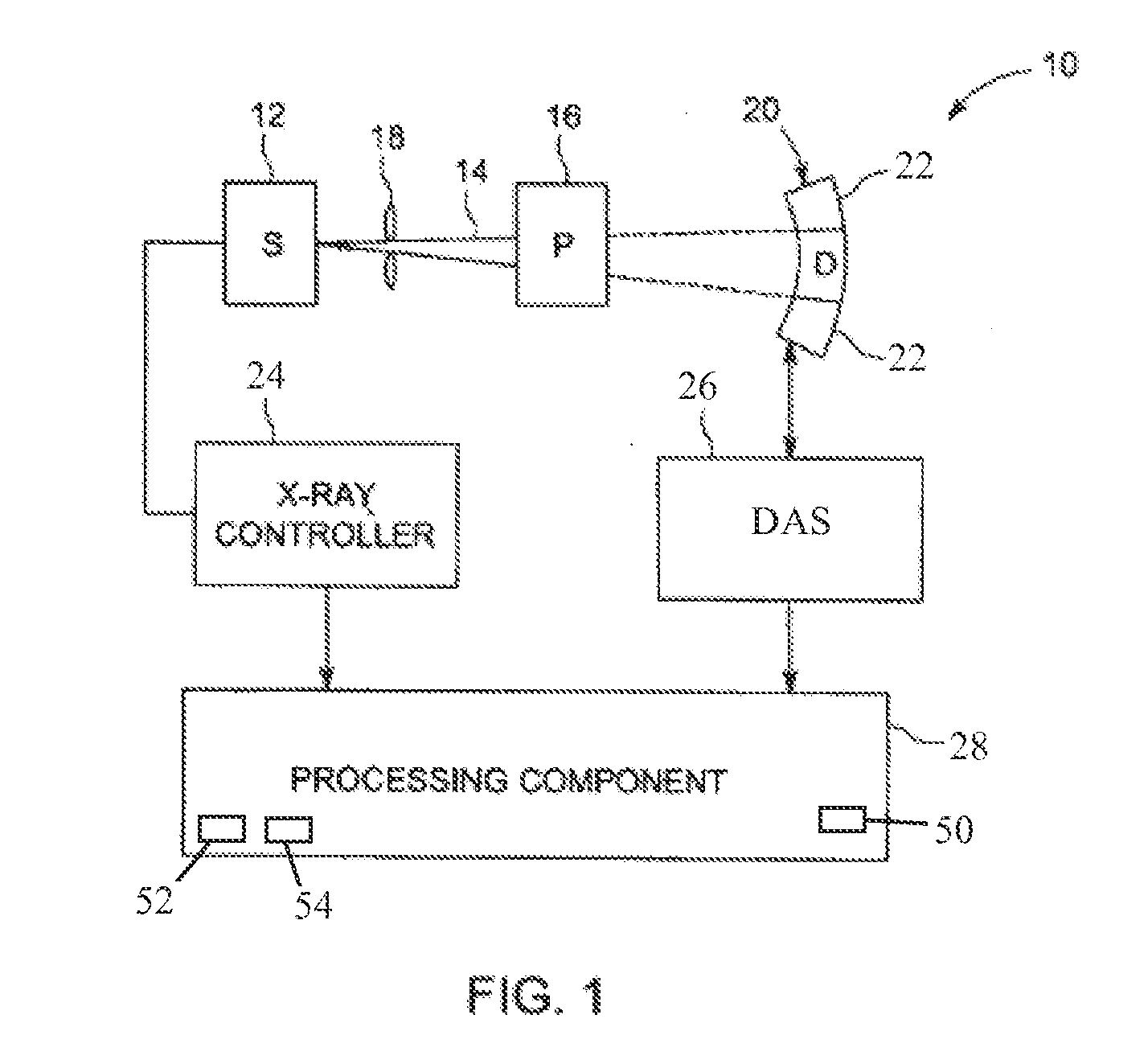
[0016]The foregoing summary, as well as the following detailed description of various embodiments, will be better understood when read in conjunction with the appended drawings. To the extent that the figures illustrate diagrams of the functional blocks of the various embodiments, the functional blocks are not necessarily indicative of the division between hardware circuitry. Thus, for example, one or more of the functional blocks (e.g., processors or memories) may be implemented in a single piece of hardware (e.g., a general purpose signal processor or a block of random access memory, hard disk, or the like) or multiple pieces of hardware. Similarly, the programs may be stand alone programs, may be incorporated as subroutines in an operating system, may be functions in an installed software package, and the like. It should be understood that the various embodiments are not limited to the arrangements and instrumentality shown in the drawings.

[0017]As used herein, an element or step...


PUM


Abstract

A method for generating an image of an obtaining a three-dimensional (3D) volume dataset of an object of interest, automatically analyzing the 3D volume dataset to generate a window level setting, automatically generating a window width setting based on the window level setting, and automatically displaying an image of the object of interest using the window width setting. An imaging system and a non-transitory computer readable medium are also described.

Description

BACKGROUND OF THE INVENTION[0001]The subject matter described herein relates generally to imaging systems, and more particularly, to a system and method for generating image window view settings.[0002]Imaging systems are widely used to generate images of various anatomical features or objects of interest. For example, computed tomography (CT) imaging systems may be utilized to generate images of a patient's vasculature, organs, bones, soft tissue, or other objects of interest. In operation, the CT imaging system projects an x-ray beam through an object being imaged, such as the patient. The x-ray beam, after being attenuated by the patient, impinges upon a detector. The intensity of the attenuated x-ray beam received at the detector is dependent upon the attenuation of the x-ray beam by the object. Each detector element of the array produces a separate electrical signal that is a measurement of the x-ray beam intensity at the detector location.[0003]The intensity measurements from t...

Claims


Application Information

Patent Timeline
IPC IPC(8): G06K9/00
CPCG06T11/008G06T5/007G06T2207/10081
Inventor RUIZ, GUILLERMOPRUVOT, CELINETREUTENARERE, JEAN-MARC
Owner GENERAL ELECTRIC CO
Why Eureka
Try Eureka