Image Guided Intra-Operative Contouring Aid

a contouring aid and image technology, applied in the field of image guided intra-operative contouring aids, can solve the problems of adding time to the overall procedure, adding to the cost of the operation, and increasing the time the patient is under anesthesia

Inactive Publication Date: 2013-12-26
DEPUY SYNTHES PROD INC
View PDF10 Cites 178 Cited by
  • Summary
  • Abstract
  • Description
  • Claims
  • Application Information

AI Technical Summary

Problems solved by technology

These adjustments add time to the overall procedure, thereby adding to the cost of the operation and the time the patient is under anesthesia.
These challenges described above are heightened during minimally invasive procedures, because the head of the polyaxial screw is not visible and the surgeon must pass the rod percutaneously.

Method used


Image

  • Image Guided Intra-Operative Contouring Aid
  • Image Guided Intra-Operative Contouring Aid
  • Image Guided Intra-Operative Contouring Aid

Examples


example

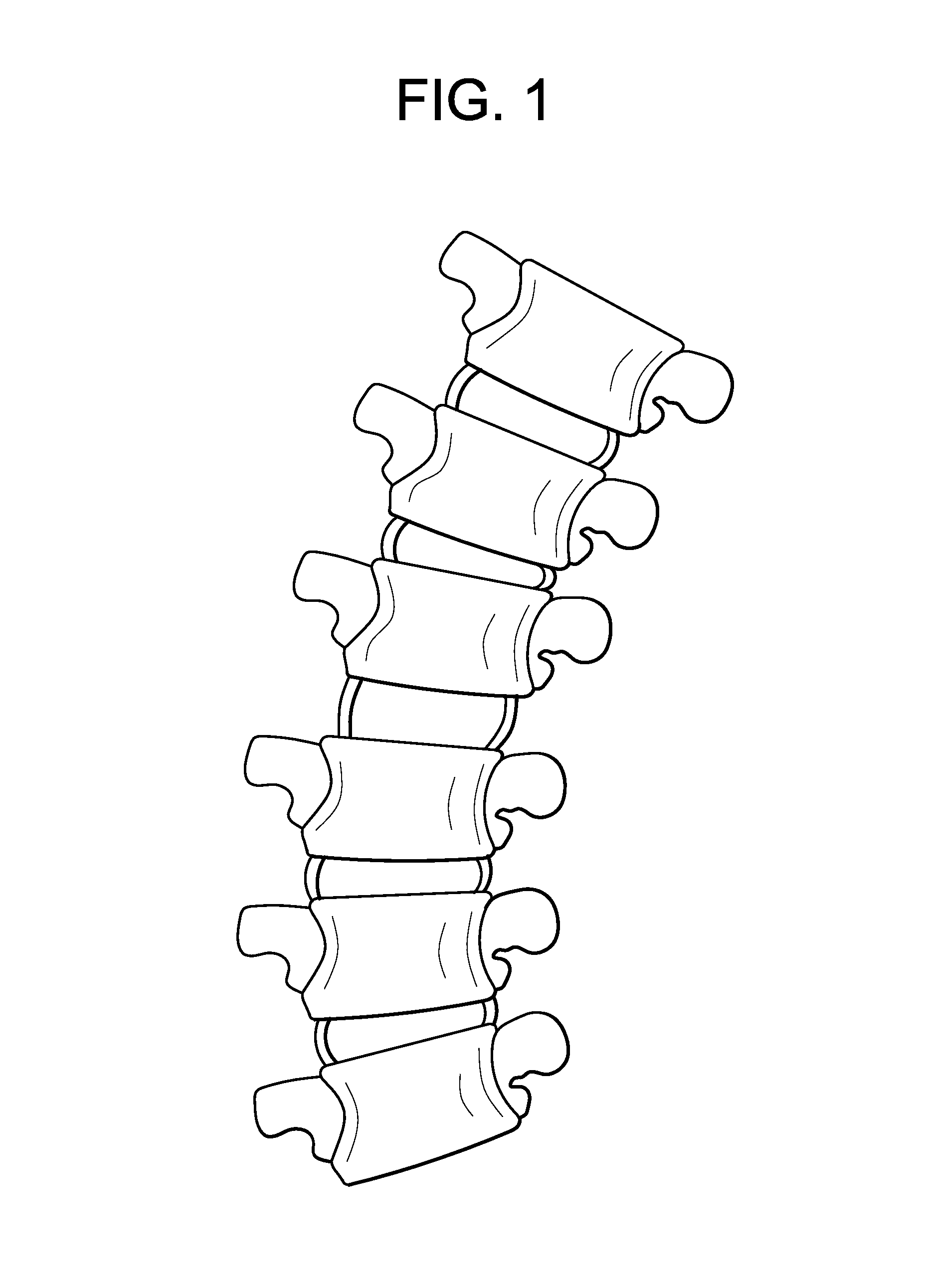
[0044]The method of the present invention is generally carried out on a patient having a deformed spine, such as a patient having a scoliotic spine. One example of a scoliotic spine is provided in FIG. 1.

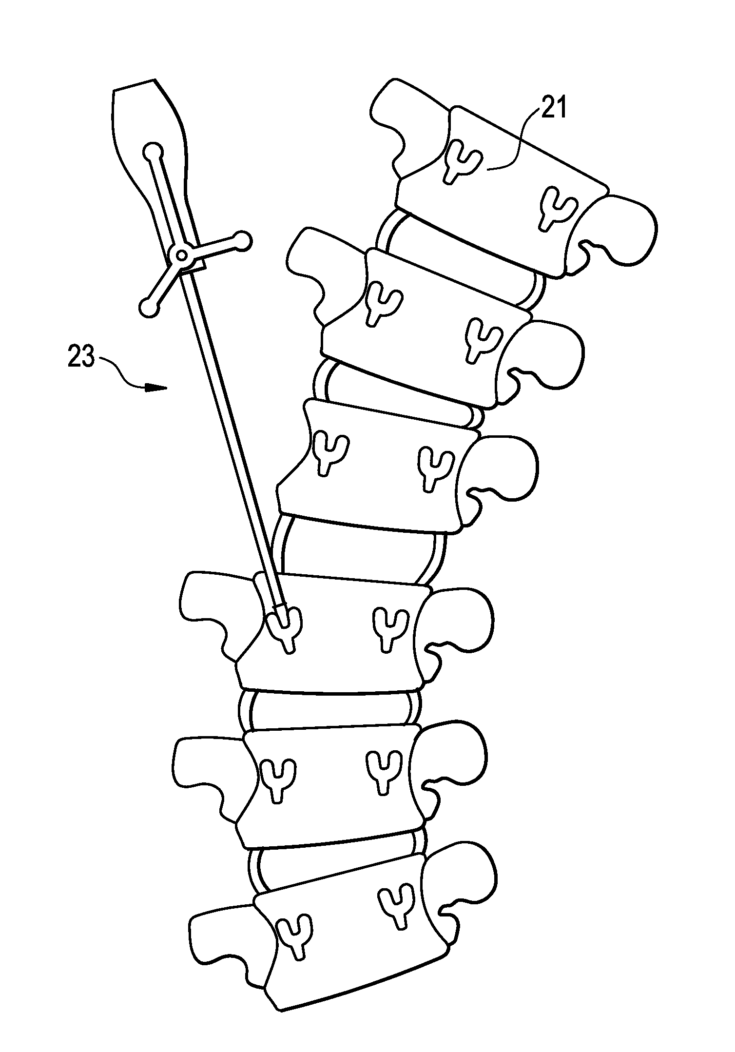
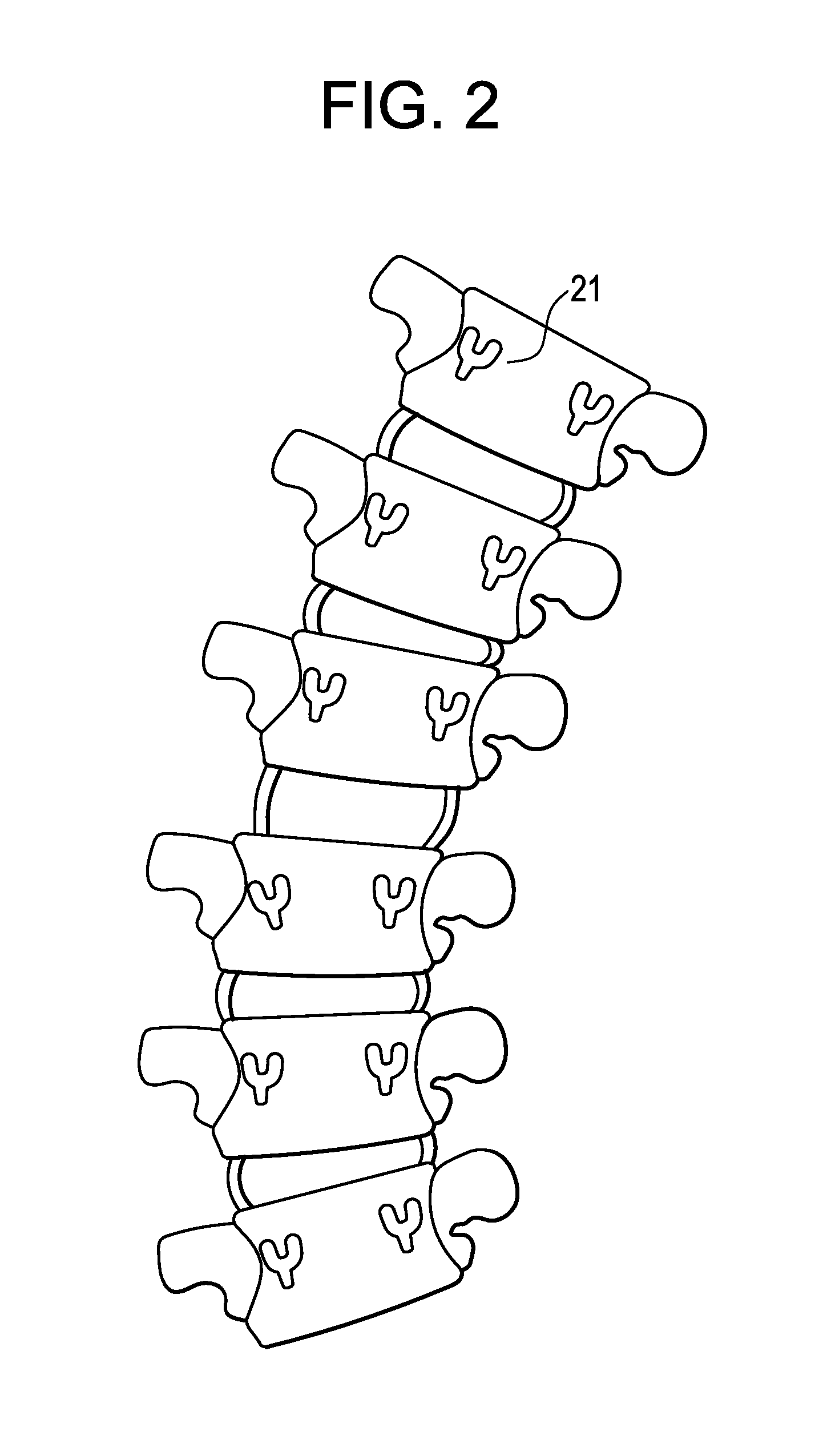
[0045]Now referring to FIG. 2, pedicle screws are placed bilaterally in the pedicles of the patient's spine. These screws can be placed via an MIS, mini-open or open approach.

[0046]Next, and now referring to FIG. 3, the distal end of the Head Locator instrument is contacted to the head of each pedicle screw. The distal end nests in the head of each screw to precisely identify the location where the central axis of a spinal rod passing through the screws would be located. With the help of the IGS computer system, the instrument identifies the location of each screw head for each side of the spine in the X, Y and Z planes.

[0047]Now referring to FIG. 4, the computer system creates a best fit curve from the points corresponding to screw head locations.

[0048]Now referring to FIG. 5, a to...


PUM


Abstract

A method of contouring spinal rods, and systems therefor. The surgeon uses image guided surgery instruments to identify the locations of the screw heads through which the rod will pass. These locations allow a computer to form a best fit line that corresponds to the shape of a rod that can pass through the screw heads. This best fit line is then displayed on a projection table from both its coronal and sagittal views. The surgeon then shapes the rod using these 2-D images as a template.

Description

BACKGROUND OF THE INVENTION[0001]Spine surgeries involving the correction of deformities or degenerative disc disease often utilize spinal rods as a means of placing the spinal column in a fixed position. These rods are used to connect the heads of pedicle screws that are placed in successive vertebrae in the spinal column around the region of deformity or degeneration. Because the spinal rod is often provided in a straight length, the surgeon must cut the rod to an appropriate length and then contour the rod to the appropriate spinal curvature.[0002]Rod contouring in complex deformity cases is a highly specialized procedure. It requires the surgeon to possess spatial cognition and an ability to visualize the partially exposed spine in three dimensions. Typically, several adjustments are made to the rod during the contouring procedure. These adjustments add time to the overall procedure, thereby adding to the cost of the operation and the time the patient is under anesthesia. Intrao...

Claims


Application Information

Patent Timeline
Patent Type & Authority Applications(United States)
IPC IPC(8): A61B17/88
CPCA61B17/7011A61B17/8863A61B2017/568A61B34/10A61B2034/108
Inventor STAD, SHAWN D.
Owner DEPUY SYNTHES PROD INC
Why Eureka
Try Eureka