Ripple extraction device, motor control apparatus, vehicle seat and ripple extraction method

a technology of extraction device and extraction method, which is applied in the direction of motor/generator/converter stopper, dynamo-electric converter control, instruments, etc., can solve the problems of increasing cost, and achieve the effect of reducing the cost of filtering, high accuracy and accurate detection

Inactive Publication Date: 2014-01-02
TS TECH CO LTD
View PDF0 Cites 21 Cited by
  • Summary
  • Abstract
  • Description
  • Claims
  • Application Information

AI Technical Summary

Benefits of technology

[0170]If the voltage signal which is converted by the current-voltage converter is a signal that is the ripple component and the high frequency component whose frequency is higher than that of the ripple component being superimposed on one another, the ripple component is detected accurately as the difference by the differential amplifier even if the frequency of each component in the current signal of the motor changes due to environmental change.
[0019]Further, because the ripple components are extracted by using the filter and the differential amplifier, a cut-off frequency variable type filter does not need to be used as the filter. Therefore, cost of the filter can be reduced.
[0020]Because the ripple extraction device is not a closed loop circuit like the feedback control circuit, the ripple components can be detected accurately even if the frequency of each component in the current signal of the motor changes transiently or drastically.

Problems solved by technology

However, using of such sensor causes increase in cost.

Method used


Image

  • Ripple extraction device, motor control apparatus, vehicle seat and ripple extraction method
  • Ripple extraction device, motor control apparatus, vehicle seat and ripple extraction method
  • Ripple extraction device, motor control apparatus, vehicle seat and ripple extraction method

Examples


first embodiment

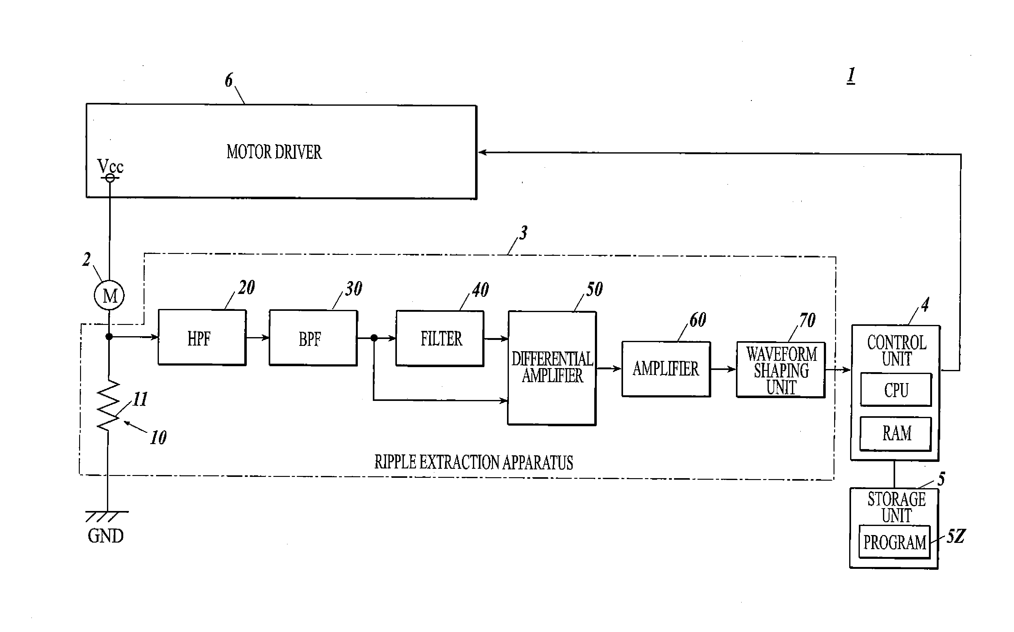
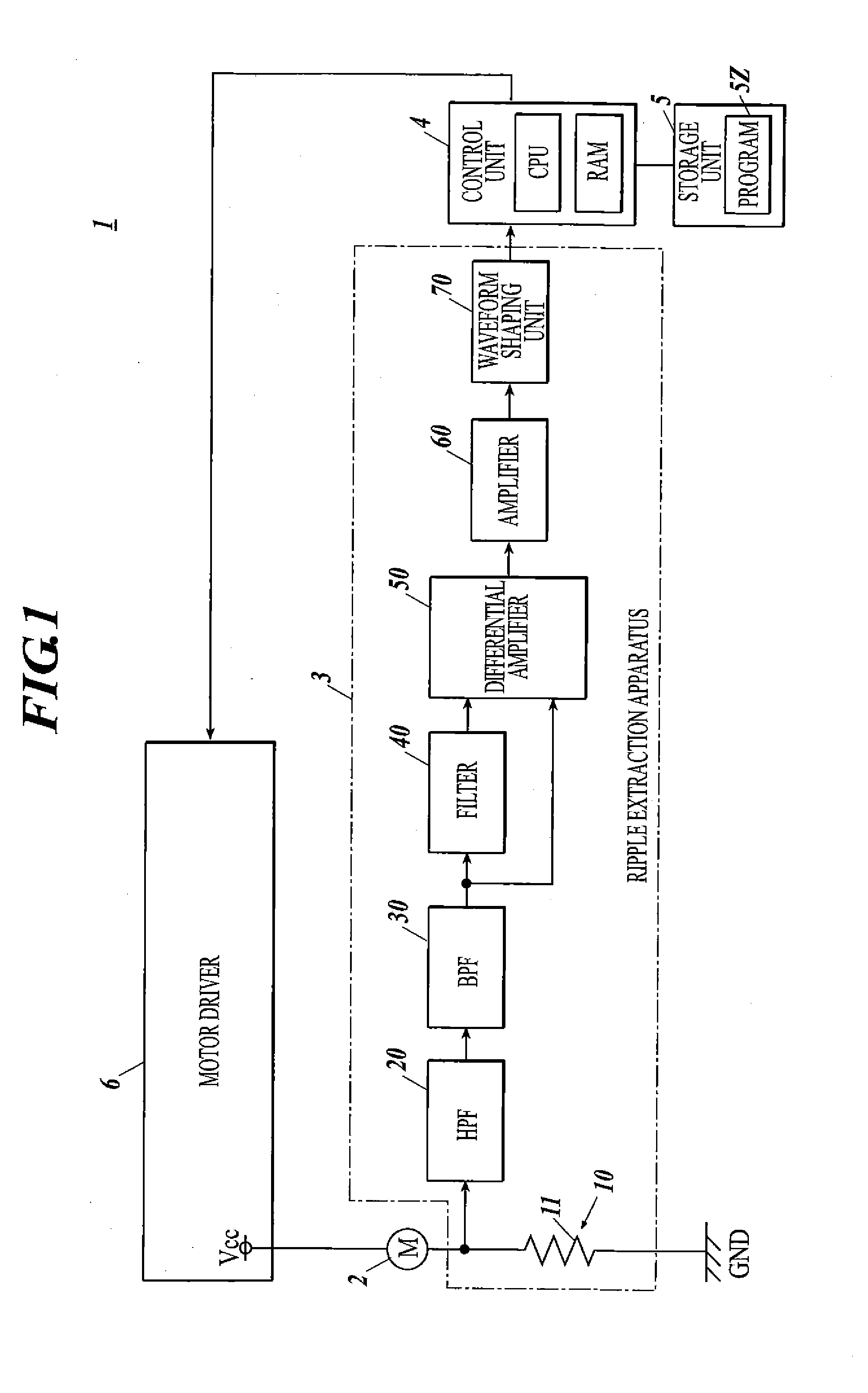
[0069]FIG. 1 is a block diagram of the motor control apparatus 1.

[0070]The motor control apparatus 1 includes a motor 2, a ripple extraction device (ripple extraction circuit) 3, a control unit 4, a storage unit 5, a motor driver 6 and such like.

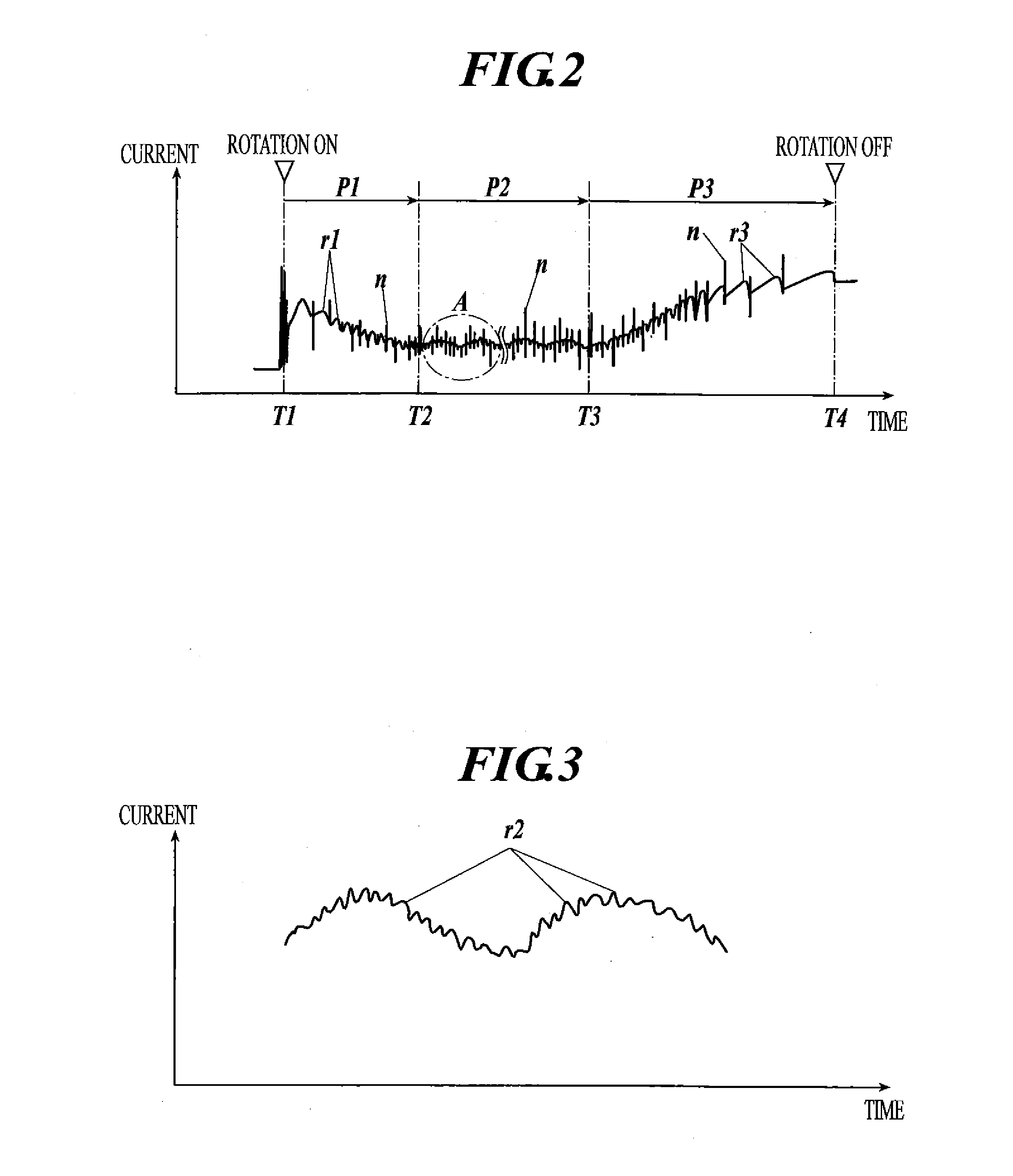
[0071]The motor 2 is a direct-current motor. If a current flows in to the motor 2, the motor 2 rotates and generates cyclic ripples in the current. The current signal of the motor 2 will be described with reference to FIGS. 2 and 3. FIG. 2 is a chart showing changes in level of the current that flows in to the motor 2 when the motor 2 is driven. FIG. 3 is a chart showing the time and the current in the A section shown in FIG. 2, the A section being enlarged.

[0072]In FIG. 2, the time T1 is the timing when the motor 2 is activated and the time T2 is the timing when the motor 2 starts to run steadily. The time T3 is the timing when the moveable unit which is driven by the motor 2 abuts the stopper or the like and the transmission mechanism whic...

second embodiment

[0179]FIG. 11 is a side view of the seat main body 190 of the vehicle seat apparatus.

[0180]As shown in FIG. 11, the vehicle seat apparatus includes the seat main body 190 on which an occupant sits. The seat main body 190 includes a plurality of moveable units. As for the moveable units of the seat main body 190, there are the back rest 193, the seat bottom 192, the head rest 194, the arm rest 195 and the leg rest 196. The moveable units of the seat main body 190 will be described in detail.

[0181]The seat bottom 192 is mounted on the rail unit 191, and the seat bottom 192 in the front-back direction by the rail unit 191. The front part of the seat bottom 192 rises and falls. The back part of the seat bottom 192 also rises and falls. The back rest 193 joins with the back end section of the seat bottom 192 by the reclining mechanism, and the back rest 193 rotates in front and back around the lower end section thereof by the reclining mechanism. The head rest 194 joins with the upper en...

example a

[0231]The control unit 104 temporarily stores the current data of the motor 102A that is input from the A / D converter 108A in the RAM 104b or the storage unit 105.


PUM


Abstract

A ripple extraction device extracts ripple components contained in a current signal of a motor. The ripple extraction device is provided with a current-voltage converter that converts a current signal of the motor into a voltage signal; a filter that filters the voltage signal converted by the current-voltage converter, and attenuates the ripple components; and a differential amplifier that obtains the difference between the voltage signal converted by the current-voltage converter and an output signal of the filter.

Description

TECHNICAL FIELD[0001]The present invention relates to a ripple extraction device, a motor control apparatus, a vehicle seat and a ripple extraction method.BACKGROUND ART[0002]In vehicle seats, electronic door mirrors, power windows and the like, moveable units are provided, and the moveable units are driven by motors. In order to accurately control the position and speed of the moveable units by control apparatuses, rotational positions of the motors while they are running need to be detected. Sensors are used to detect the rotational positions of the motors. That is, a sensor (for example, a Hall device, an encoder, a reed switch sensor) is provided in a motor, for example, and a signal which synchronizes with the rotation of the motor which is running is output by the sensor and the output signal of the sensor is input to the control apparatus via the detection circuit (for example, a comparator or an AD converter).[0003]However, using of such sensor causes increase in cost. In vi...

Claims


Application Information

Patent Timeline
Patent Type & Authority Applications(United States)
IPC IPC(8): H02P7/00B60N2/02
CPCH02P7/0094B60N2/02H02P7/29B60N2/0272B60N2/02246
Inventor TANAKA, SOICHIROKOWATA, KOHEIITO, TAKAYOSHISHIMAZAKI, HAYATO
Owner TS TECH CO LTD
Why Eureka
Try Eureka