
Magnetic device and method of manufacturing the same

a technology of magnetic devices and cores, applied in the manufacture of magnets, magnetic bodies, magnetic cores, etc., can solve the problems of poor c-face cracking, easy cracking of iron cores, and difficult to accurately position coils, so as to improve the adhesion strength and reduce the surface utility rate of the circuit board. , the effect of increasing the surface utility ra

Active Publication Date: 2014-01-02
CYNTEC
View PDF6 Cites 63 Cited by
  • Summary
  • Abstract
  • Description
  • Claims
  • Application Information

AI Technical Summary

Benefits of technology

This patent describes a new design for a magnetic device with several technical benefits. Firstly, the design allows for better attachment to the circuit board which increases its overall strength. Secondly, without any side-mounted electrodes, this makes the device smaller and more efficient use of space on the circuit board. Thirdly, the design offers flexibility when adapting different shapes and sizes of coils while still maintaining optimal performance. Finally, the leads used in the design offer easy solderability and positioning of the core body during assembly.

Problems solved by technology

The technical problem addressed by this patent is how to improve the accuracy and reliability of small and thin inductors used in electronic devices. Previous designs had issues with bending stresses causing damage or poor performance, while others required complex processes for production.

Method used


Image

  • Magnetic device and method of manufacturing the same
  • Magnetic device and method of manufacturing the same
  • Magnetic device and method of manufacturing the same

Examples


Embodiment Construction

[0026]The detailed explanation of the present invention is described as following. The described preferred embodiments are presented for purposes of illustrations and description and they are not intended to limit the scope of the present invention.

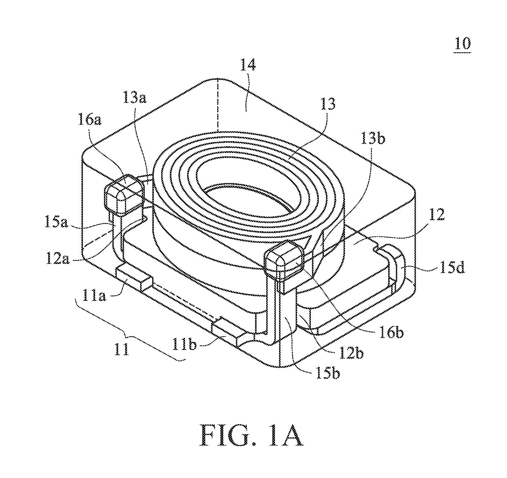
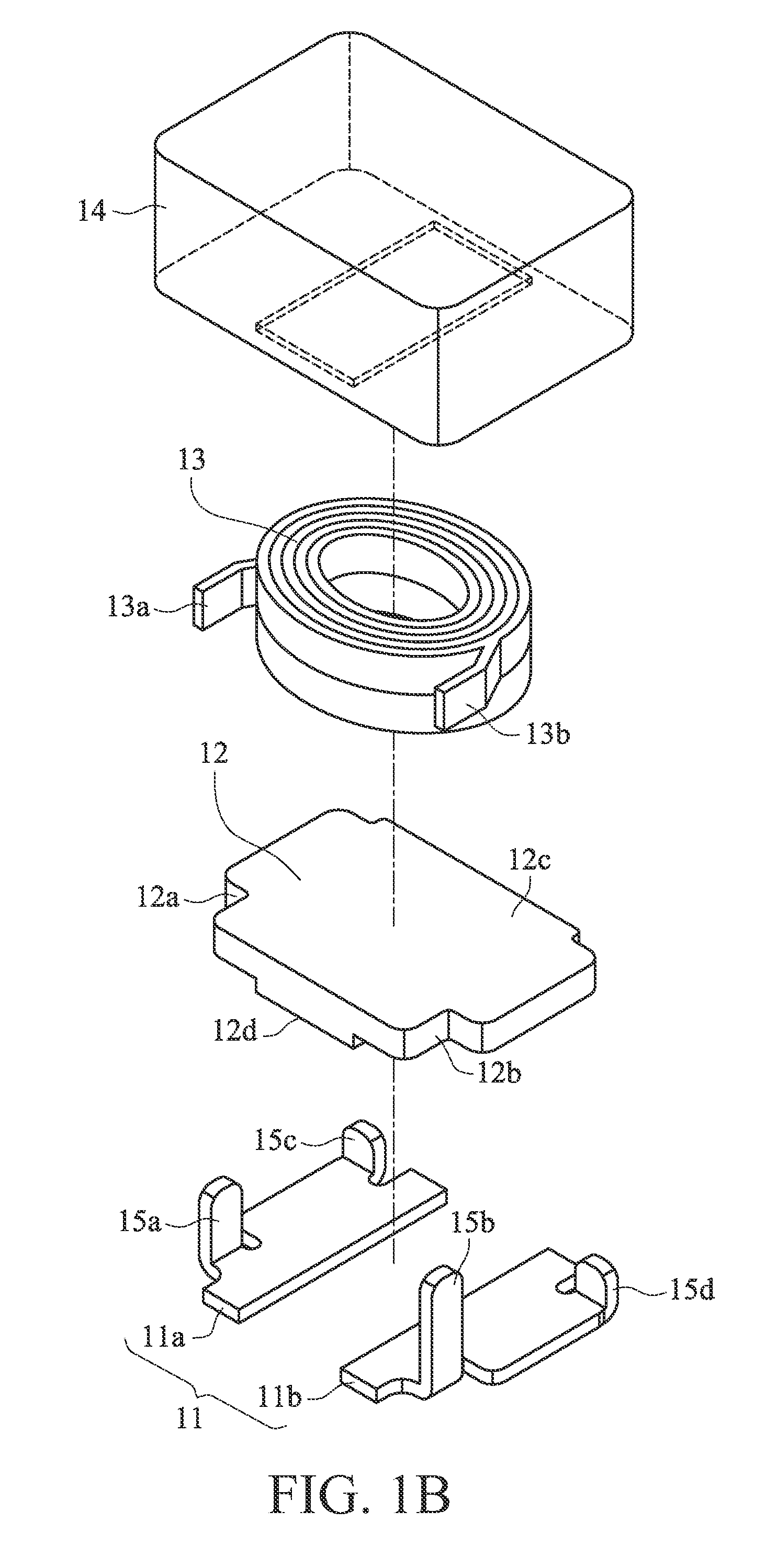
[0027]The present invention discloses a magnetic device in which a first portion and a second portion of a lead frame respectively are electrically connected with a first terminal and a second terminal of a coil through a first through opening and a second through opening of a core body to serve as a first electrode and a second electrode on the bottom of the magnetic device.

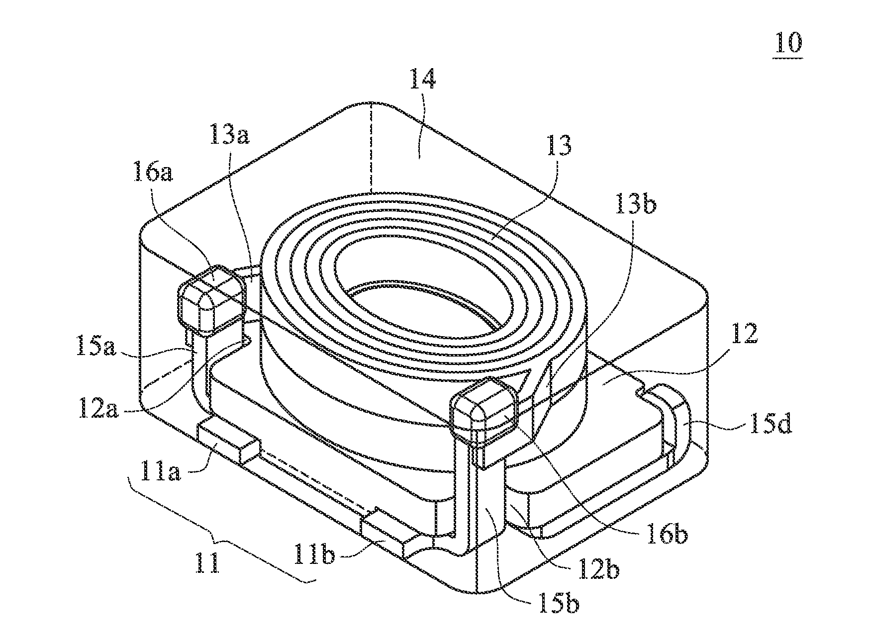
[0028]FIG. 1A is a schematic view of a magnetic device 10 in the present invention. FIG. 1B is an exploded schematic view of the magnetic device 10 shown in FIG. 1A. FIG. 1C is a bottom schematic view of the magnetic device 10 shown in FIG. 1A. FIG. 1D is an exploded schematic view of the magnetic device 10, wherein the first core body is a T-core body. FIG. 1E is a s...


PUM

PropertyMeasurementUnit
Electrical conductoraaaaaaaaaa

Abstract

A magnetic device comprises a lead frame, a first core body and a coil. The lead frame has a first portion and a second portion spaced apart from the first portion. A first core body is disposed on the lead frame, wherein the first core body comprises a first through opening and a second through opening. A coil is disposed on the first core body, wherein the coil has a first terminal and a second terminal, wherein the first portion is electrically connected with the first terminal via the first through opening, and the second portion is electrically connected with the second terminal via the second through opening, respectively.

Description


Claims


Application Information

Patent Timeline
Owner CYNTEC
Learn More