Low-Power Capacitive Sensor Monitoring and Method

a capacitive sensor and low-power technology, applied in the direction of instruments, computing, electric digital data processing, etc., can solve the problems of high associated power consumption, inability to determine if a touch is present, and inability to use a touch in real time, so as to achieve less complex hardware and software, less power consumption, and less power consumption

Inactive Publication Date: 2014-01-02
TEXAS INSTR INC
View PDF9 Cites 54 Cited by
  • Summary
  • Abstract
  • Description
  • Claims
  • Application Information

AI Technical Summary

Benefits of technology

[0034]It is another object of the invention to provide a touch screen controller which can detect the presence of a touch on a touch screen panel substantially faster than the prior art and which also requires substantially less power consumption to detect presence of the touch than the prior art.
[0035]It is another object of the invention to provide a touch screen controller which can detect the presence of a touch on a touch screen panel substantially faster than the prior art and which also requires substantially less power consumption to detect presence of the touch, and which nevertheless requires less complex hardware and software than the prior art.

Problems solved by technology

This consumes substantially more power than would be desirable in most battery-powered applications, such as cell phone applications.
There is no practical way of determining if a touch is occurring except to detect its presence by frequently performing a full touch screen panel scan.
The high amount of associated power consumption required for such frequent full panel scanning merely to determine if a touch is present is very undesirable.

Method used


Image

  • Low-Power Capacitive Sensor Monitoring and Method
  • Low-Power Capacitive Sensor Monitoring and Method
  • Low-Power Capacitive Sensor Monitoring and Method

Examples


Embodiment Construction

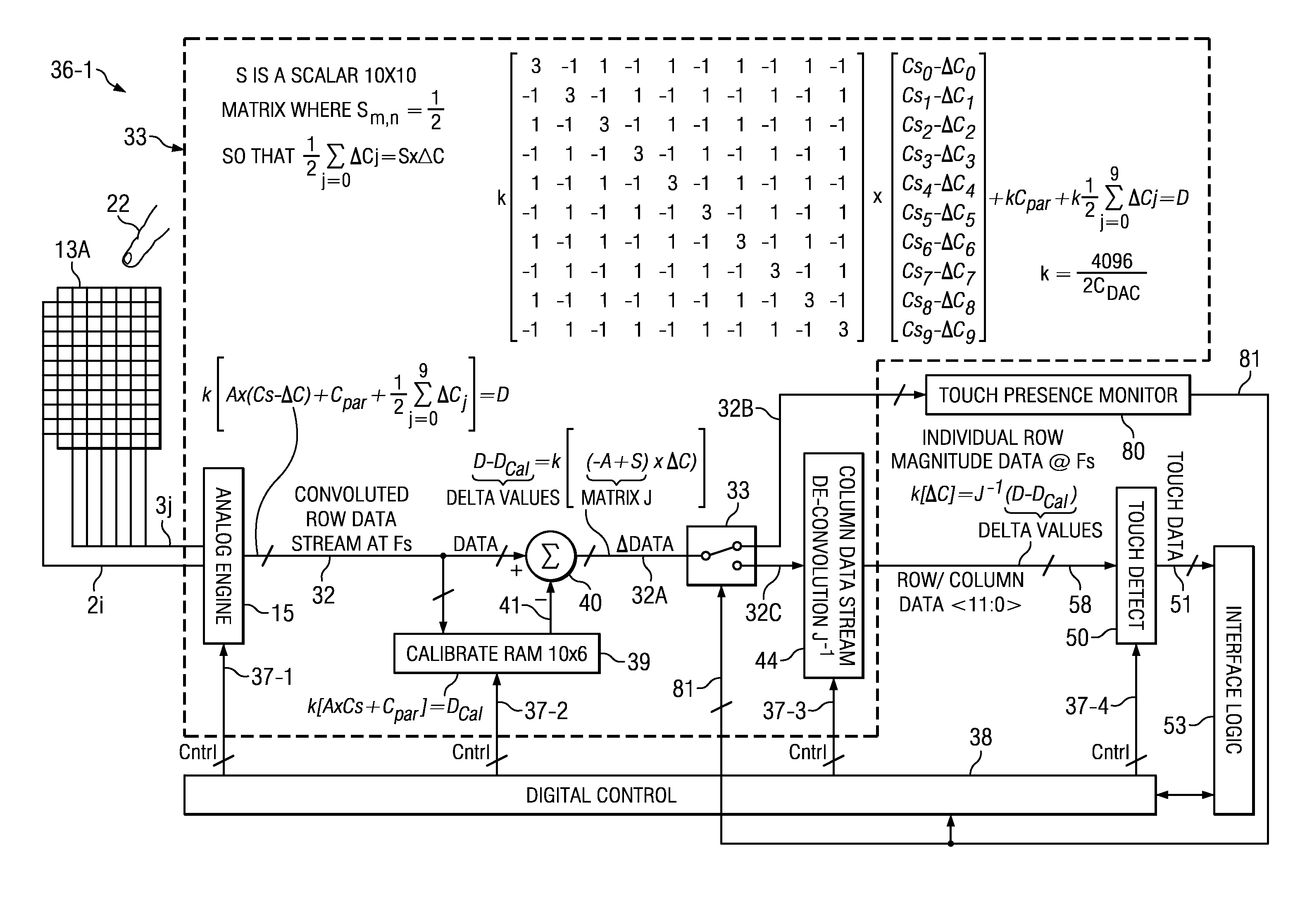
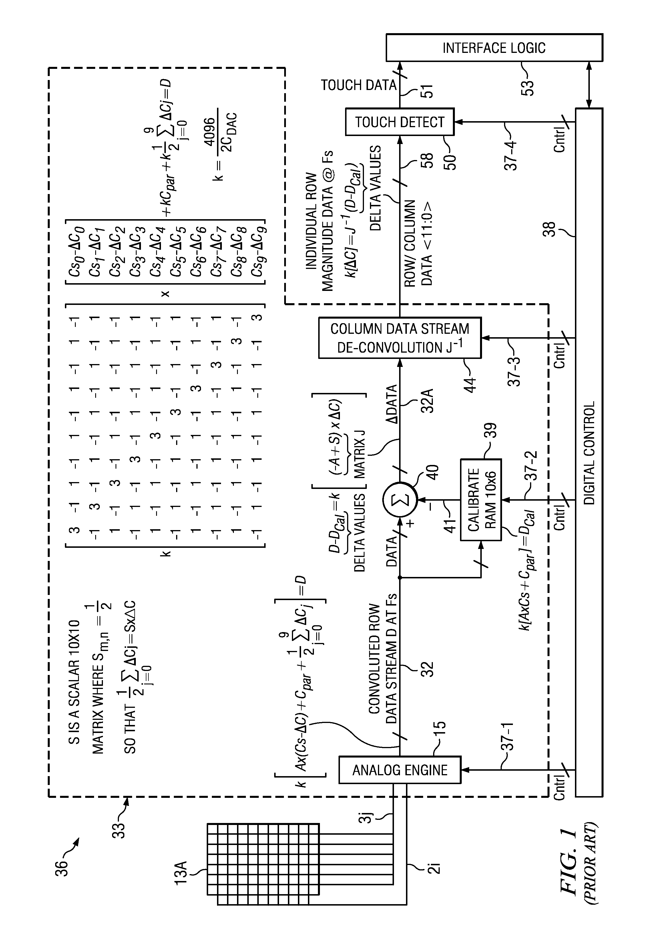
[0062]Touch screen controller system 36-1 in FIG. 5 includes everything in Prior Art FIG. 1, and further includes touch presence monitoring circuit 80, which operates during a low-power “touch presence monitoring mode” to detect the presence of a valid touch on touch screen panel 13A. The portions of touch screen controller 36-1 which are substantially the same as the portions shown in Prior Art FIG. 1 operate essentially the same as in prior art touch screen controller 36 of FIG. 1.

[0063]Touch screen controller system 36-1 of FIG. 5 has three main modes of operation, including the foregoing touch presence monitoring mode, the “full panel scanning mode” previously described with respect to Prior Art FIG. 1, and also a “deep sleep” mode. The touch presence monitoring mode is a low-power mode in which an application device (such as a cell phone, computer tablet, remote controller, or other battery-operated device having a touch screen) operates to periodically scan touch screen panel ...


PUM


Abstract

A touch screen controller produces a first signal (DATA) representative of a self capacitance (Cselfj) of a touch screen (13A) during a presence scanning mode and representative of mutual capacitances (Cmij) of the screen during a location scanning mode. The first signal is calibrated during the presence scanning and during the location scanning to produce a second signal (ΔDATA) which may represent either self-capacitance changes (ΔCselfj) caused by proximity of an element (22) during presence scanning or mutual capacitance changes (ΔCmij) caused the element during location scanning. The second signal is operated upon during presence scanning to determine to determine proximity of the element relative to the screen and during location scanning to produce a magnitude map of the mutual capacitance changes.

Description

BACKGROUND OF THE INVENTION[0001]The present invention relates generally to capacitive sensor touch screen panels, and more particularly to improved control circuitry and techniques for determining the presence or absence of a touch on a touch screen panel faster and with less power than prior control circuitry for capacitive sensor touch screen panels.[0002]The closest prior art is believed to include commonly assigned, published, and allowed pending US patent application entitled “De-convolution-based Capacitive Touch Detection Circuit and Method” by Cormier, Jr. et al., application Ser. No. 12 / 587,453, filed Oct. 7, 2009, published Sep. 30, 2010, Publication No. 2010 / 0244859 (hereinafter, “the '859 application”), which is entirely incorporated herein by reference. The foregoing application describes use of a “3q” scanning technique wherein scanning of each “node” of a touch screen panel involves transfer of 3 charge packets to achieve a linear combining of charges, referred to he...

Claims


Application Information

Patent Timeline
Patent Type & Authority Applications(United States)
IPC IPC(8): G06F3/044
CPCG06F3/044G06F3/0418G06F3/041662G06F3/0446
Inventor CORMIER, JR., RONALD F.SNEDEKER, MICHAEL D.
Owner TEXAS INSTR INC
Why Eureka
Try Eureka