Image processing device and image processing method
a technology of image processing and image, applied in the direction of selective content distribution, electrical equipment, television systems, etc., can solve the problem of reducing the buying motivation of viewers
- Summary
- Abstract
- Description
- Claims
- Application Information
AI Technical Summary
Benefits of technology
Problems solved by technology
Method used
Image
Examples
first embodiment
[Configuration Example of First Embodiment of Encoding Device]
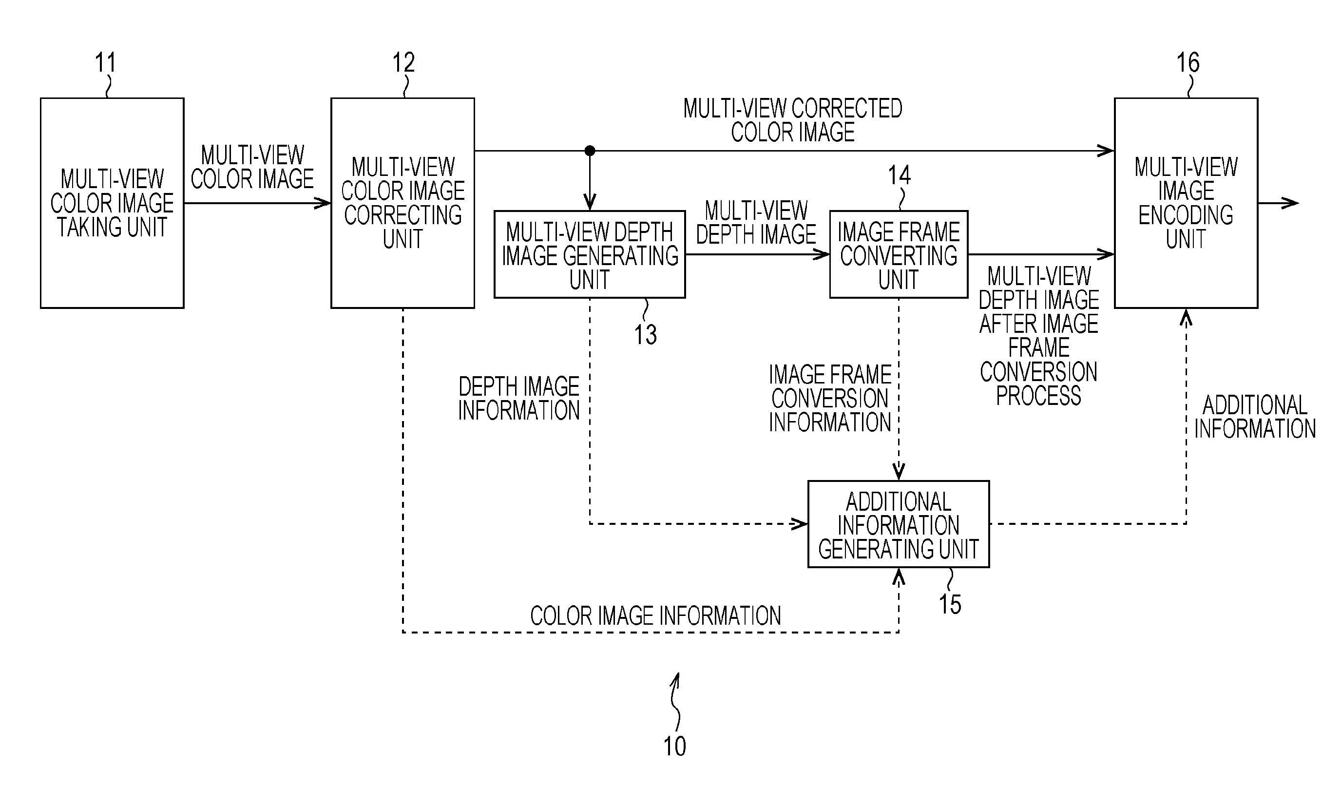
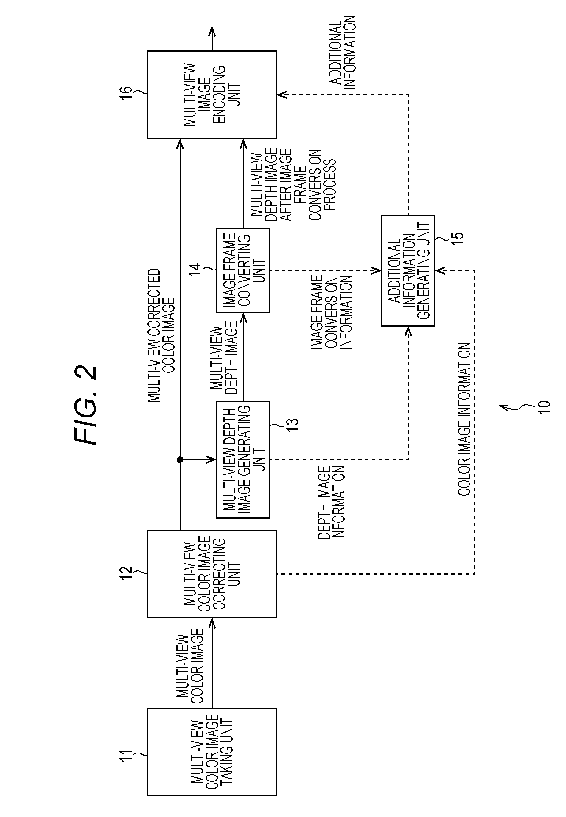
[0062]FIG. 2 is a block diagram illustrating a configuration example of a first embodiment of an encoding device as an image processing device to which this technology is applied.
[0063]An encoding device 10 in FIG. 2 is composed of a multi-view color image taking unit 11, a multi-view color image correcting unit 12, a multi-view depth image generating unit 13, an image frame converting unit 14, an additional information generating unit 15, and a multi-view image encoding unit 16.
[0064]The encoding device 10 collectively encodes color images and depth images of multiple viewpoints and adds predetermined information thereto to transmit.
[0065]Specifically, the multi-view color image taking unit 11 of the encoding device 10 takes color images of multiple viewpoints and supplies the same to the multi-view color image correcting unit 12 as the multi-view color image.
[0066]The multi-view color image correcting unit 12 performs c...
second embodiment
[Configuration Example of One Embodiment of Encoding Device]
[0161]FIG. 14 is a block diagram illustrating a configuration example of a second embodiment of an encoding device as an image processing device to which this technology is applied.
[0162]In the configuration illustrated in FIG. 14, the same reference sign is assigned to the configuration the same as that in FIG. 2. Overlapping description is appropriately omitted.
[0163]A configuration of an encoding device 50 in FIG. 14 is different from the configuration in FIG. 2 principally in that a multi-view image encoding unit 51 is provided in place of a multi-view image encoding unit 16. The encoding device 50 in FIG. 14 includes a resolution flag and image frame conversion information out of additional information in a Subset SPS and includes information other than the resolution flag and the image frame conversion information in SEI to transmit.
[0164]Specifically, the multi-view image encoding unit 51 of the encoding device 50 en...
third embodiment
[0219][Description of Computer to which this Technology is Applied]
[0220]A series of processes described above may be performed by hardware or by software. When a series of processes are performed by the software, a program, which composes the software, is installed on a multi-purpose computer and the like.
[0221]FIG. 25 illustrates a configuration example of one embodiment of the computer on which the program, which executes a series of processes described above, is installed.
[0222]The program may be recorded in advance in a storage unit 808 and a ROM (read only memory) 802 as a recording medium embedded in the computer.
[0223]Alternatively, the program may be stored (recorded) in a removable medium 811. Such removable medium 811 may be provided as so-called packaged software. Herein, the removable medium 811 includes a flexible disk, a CD-ROM (compact disc read only memory), an MO (magneto-optical) disk, a DVD (digital versatile disc), a magnetic disk, a semiconductor memory and the...
PUM
 Abstract
Description
Claims
Application Information
 - R&D
- Intellectual Property
- Life Sciences
- Materials
- Tech Scout
- Unparalleled Data Quality
- Higher Quality Content
- 60% Fewer Hallucinations
Browse by: Latest US Patents, China's latest patents, Technical Efficacy Thesaurus, Application Domain, Technology Topic, Popular Technical Reports.
© 2025 PatSnap. All rights reserved.Legal|Privacy policy|Modern Slavery Act Transparency Statement|Sitemap|About US| Contact US: help@patsnap.com


