Image forming apparatus, image forming system, and program
- Summary
- Abstract
- Description
- Claims
- Application Information
AI Technical Summary
Benefits of technology
Problems solved by technology
Method used
Image
Examples
first embodiment
Configuration of the Image Forming System in the First Embodiment
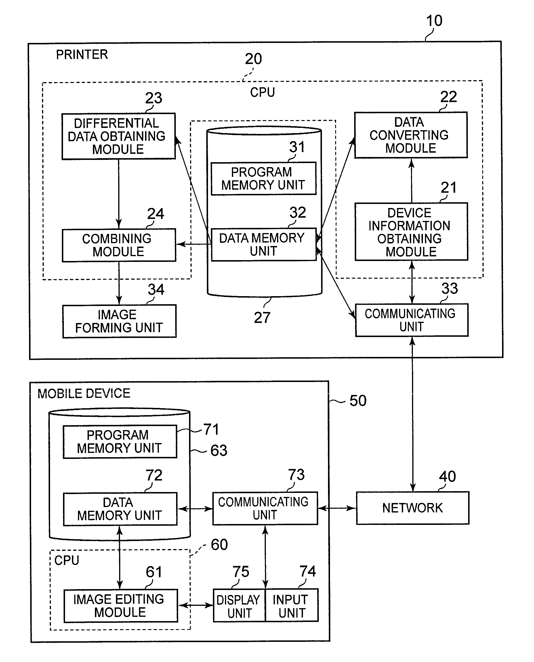
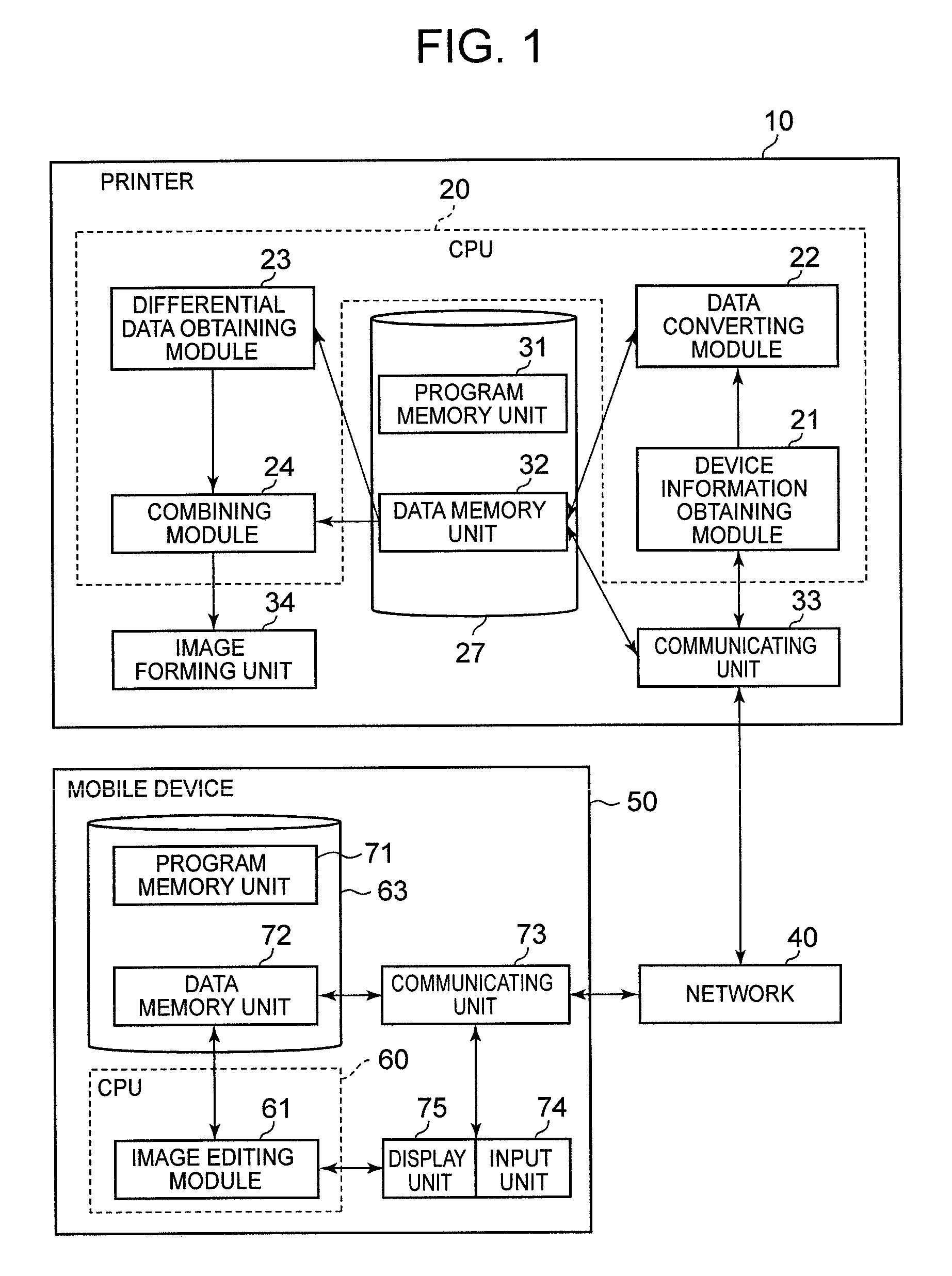
[0043]The configuration of a first embodiment of the image forming system is shown FIG. 1. The image forming system in FIG. 1 may include a printer 10 and one or more mobile device(s) 50 such as, for example, a PDA (Personal Digital Assistant), a cell phone or a smart phone, as an external device. The printer 10 and the mobile device(s) 50 are connected via a network 40.
[0044]The printer 10 may include a CPU (Central Processing Unit) 20, a storage unit 27, a communicating unit 33, and an image forming unit 34. The CPU 20 controls units and modules in the printer 10. The storage unit 27 stores, for example, computer program(s), as well as related or other information. The computer program(s) may include a control program to control the printer 10. For example, in embodiments where modules 21-24 are implemented as computer programs, the storage unit 27 may store the modules 21-24 and data used by the modules 21-24. The s...
second embodiment
Configuration of the Image Forming System in the Second Embodiment
[0088]The image forming system in FIG. 18 includes a printer 10A and mobile device(s) 50.
[0089]The printer 10A may include a CPU 20A, a storage unit 27, a communicating unit 33, and an image forming unit 34. The CPU 20A controls units and modules in the printer 10A. The CPU 20A may execute control programs stored in the program memory unit, and oversee functions of the printer 10A. For example, the CPU 20A may include the device information obtaining module 21, the data converting module 22, the differential data obtaining module 23, the combining module 24, and the image exchange module 25. The image exchange module 25 may exchange the image data that the data memory unit 32 stores for the combined image data that the combining module 24 obtains.
Processing of the Image Forming System The processing for obtaining the displayed image may have the same processing as the first embodiment. The processing of printing is de...
third embodiment
Configuration of the Image Forming System in the Third Embodiment
[0096]The image forming system in FIG. 23 may include a printer 10B and one or more mobile device(s) 50.
[0097]Referring to FIG. 23, the printer 10B may include the CPU 20, the storage unit 27, the communicating unit 33, the image forming unit 34, and a rasterizer module 35. The rasterizer module 35 may be connected with the data memory unit 32 in the storage unit 27. The CPU 20 may control the rasterizer module 35, and the rasterizer module 35 may rasterize document(s) data so as to be printed. In other words, the rasterizer module 35 may create the image data from document(s) data.
[0098]The mobile device 50 may obtain and edit the displayed image 85 after the rasterizer module 35 rasterizes the document data and the processing of obtaining the displayed image is performed as described above, although document data is not image data.
PUM
 Abstract
Description
Claims
Application Information
 - R&D
- Intellectual Property
- Life Sciences
- Materials
- Tech Scout
- Unparalleled Data Quality
- Higher Quality Content
- 60% Fewer Hallucinations
Browse by: Latest US Patents, China's latest patents, Technical Efficacy Thesaurus, Application Domain, Technology Topic, Popular Technical Reports.
© 2025 PatSnap. All rights reserved.Legal|Privacy policy|Modern Slavery Act Transparency Statement|Sitemap|About US| Contact US: help@patsnap.com


