
Accessory, camera, accessory control method, accessory control program, and camera control program

a technology for controlling programs and accessories, applied in the field of accessory control methods, camera control methods, and accessory control methods, can solve problems such as difficulty in appropriately setting the turn-on possible time, deteriorating usability of the system, and affecting the convenience of users, so as to achieve the effect of improving convenien

Inactive Publication Date: 2014-01-09
NIKON CORP
View PDF1 Cites 35 Cited by
  • Summary
  • Abstract
  • Description
  • Claims
  • Application Information

AI Technical Summary

Benefits of technology

This patent aims to provide an accessory, method, and program for controlling the time it takes for an illumination light to turn on. This improves the convenience of using the accessory and camera. Additionally, it allows for the appropriate setting of the illumination light's turn-on time.

Problems solved by technology

When the camera system, for example, does not respond to a user operation or causes a response delay, usability of the system is deteriorated.
In addition, since the accessory has a battery built-in or is supplied with power from the camera through a cable, convenience deteriorates.
In such a case, the turn-on possible time of the illumination light emitting section is required to be set, but it is difficult to appropriately set the turn-on possible time.

Method used


Image

  • Accessory, camera, accessory control method, accessory control program, and camera control program
  • Accessory, camera, accessory control method, accessory control program, and camera control program
  • Accessory, camera, accessory control method, accessory control program, and camera control program

Examples


first embodiment

[0088]Exemplary embodiments of the present invention will be described below in detail. In the following description, components having the same or similar structure or functions are assigned the same reference numerals and signs, and the description thereof may be simplified or omitted.

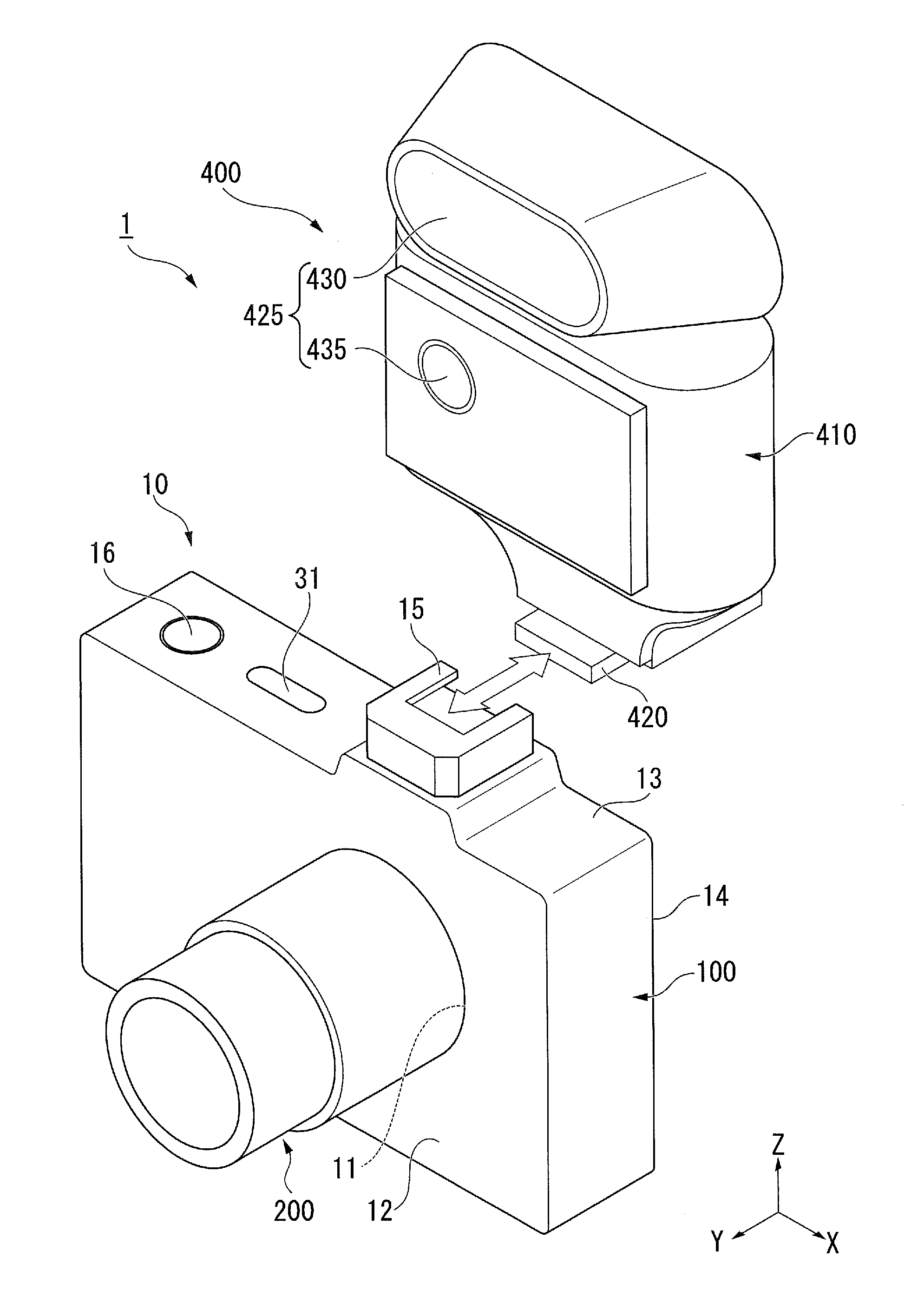
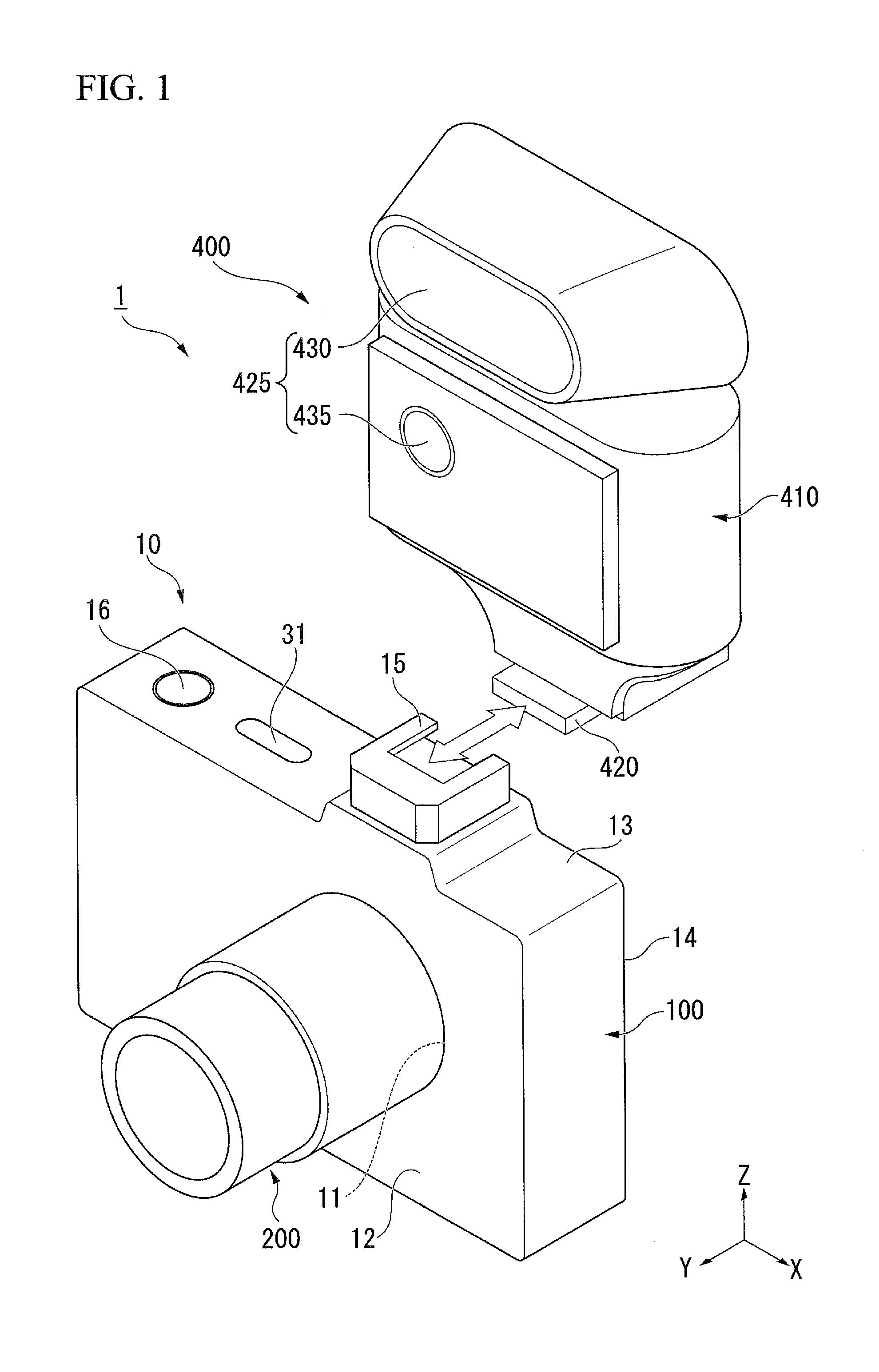
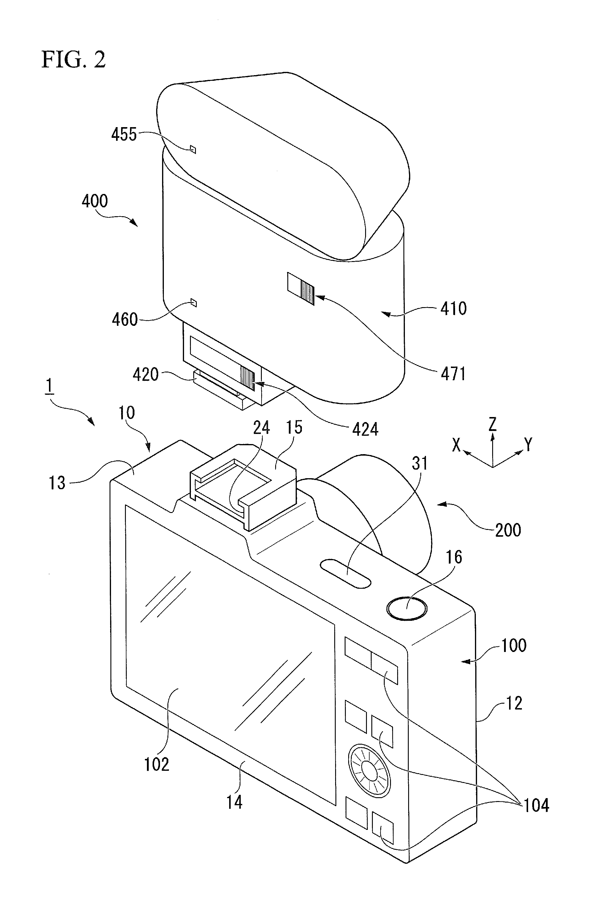
[0089]FIG. 1 is a diagram illustrating the appearance of a camera system 1 according to the present embodiment. FIG. 2 is a diagram illustrating the appearance of the camera system 1 when viewed from the side opposite to FIG. 1.

[0090]The camera system 1 shown in FIGS. 1 and 2 includes a camera 10 and an accessory 400. The camera 10 includes a camera body 100 and an image capture lens 200. The accessory 400, for example, has a light-emitting function, and is an external illumination device (attachable to and detachable from the camera 10) used to illuminate a subject. The camera 10 can communicate with the accessory 400 to control the accessory 400. The camera system 1 captures an image of the subject...

modified example 1

[0458]First, Modified Example 1 will be described. FIG. 25 is a diagram illustrating a procedure of processes in an initial communication sequence of Modified Example 1. A series of processes in Modified Example 1 is different from a series of processes described with reference to FIG. 12, in that after the process of step S204, it is determined in step S260 whether information is received normally from the accessory control section 440.

[0459]In Modified Example 1, subsequently to the reception of the accessory initial state information from the accessory control section 440, for example, in step S204, the camera control section 170 determines whether information is received normally from the accessory control section 440 (step S260).

[0460]Explaining for more details, in step S260, when the accessory initial state information received in step S204 includes information (for example, battery presence or absence information and function type information) of items designated by the tran...

modified example 2

[0474]Next, Modified Example 2 will be described. FIG. 26 is a diagram illustrating a procedure of processes in a power supply control of Modified Example 2. A series of processes in Modified Example 2 is different from a series of processes described with reference to FIG. 14, in that after the process of step S250, it is determined in step S262 whether the information is received normally from the accessory control section 440.

[0475]In Modified Example 2, when it is determined in step S250 that the accessory 400 does not have a battery (step S250: NO), the camera control section 170 determines whether the battery “absence” information is received normally in step S262. In step S262, the camera control section 170 determines that the information is received normally (step S262: Yes) when the battery “absence” information is received in step S204, and continues the supply of power to the accessory 400 started in step S103. In addition, in step S262, the camera control section 170 de...


PUM


Abstract

Provided is an accessory which is capable of communicating with a camera, including an illumination light emitting section that emits illumination light, a nonvolatile memory that stores light-emittable time information indicating the longest time for which the illumination light emitting section is capable of continuously emitting the illumination light, and an accessory control section that transmits the light-emittable time information stored in the nonvolatile memory to the camera.

Description

CROSS-REFERENCE TO RELATED APPLICATION[0001]This is a Continuation Application of International Application No. PCT / JP2012 / 068136, filed on Jul. 17, 2012, which claims priority to Japanese Patent Application No. 2011-158870, filed Jul. 20, 2011, Japanese Patent Application No. 2011-158872, filed Jul. 20, 2011, Japanese Patent Application No. 2011-161358, filed Jul. 22, 2011, Japanese Patent Application No. 2011-203702, filed Sep. 16, 2011, U.S. Provisional Application No. 61 / 589,530, filed Jan. 23, 2012, U.S. Provisional Application No. 61 / 589,600, filed Jan. 23, 2012, and U.S. Provisional Application No. 61 / 589,593, filed Jan. 23, 2012, the contents of which are incorporated herein by reference.BACKGROUND[0002]1. Field of the Invention[0003]The present invention relates to an accessory, a camera, an accessory control method, an accessory control program, and a camera control program.[0004]2. Description of the Related Art[0005]Cameras are often used with an accessory such as a flas...

Claims


Application Information

Patent Timeline
IPC IPC(8): H04N5/225
CPCH04N5/2256G03B2206/00G03B2215/056G03B17/566H04N23/56H04N23/67H04N23/651
Inventor OZONE, AKIHIROIMAFUJI, KAZUHARUMURAMATSU, KEIKOKUMAZAWA, IZUMIIDE, YUSUKE
Owner NIKON CORP
Learn More