LED tube lamp structure

a technology of led tubes and lamps, which is applied in the direction of lighting device details, light sources, lighting and heating apparatus, etc., can solve the problems of shortened service life of led lamps, increased weight and manufacturing costs of led tubes, and reduced lighting efficiency, etc., to achieve the effect of prolonging the service li

Inactive Publication Date: 2014-01-09
FIN CORE +1
View PDF2 Cites 61 Cited by
  • Summary
  • Abstract
  • Description
  • Claims
  • Application Information

AI Technical Summary

Benefits of technology

[0011]When the heat-dissipation metal base is attached to the glass tube, it is brought by the upward tension to tightly contact with the inner surface of the glass tube without becoming dropped, deformed or separated from the glass tube when the LED tube lamp is ligh...

Problems solved by technology

The produced heat must be timely removed from the LED lamp, lest LED chips in the LED lamp should have an excessively high interface temperature to result in reduced lighting efficiency and shortened service life of the LED lamp.
The conventional LED tube lamp has the following disadvantages in terms of its manufacturing and applications:(1) While the lamp shell has effectively increased heat-dissipation area, it requires increased amount of metal material to manufacture to thereby increase the weight and the manufacturing cost of the LED tube lamp;(2) The lamp...

Method used


Image

  • LED tube lamp structure
  • LED tube lamp structure
  • LED tube lamp structure

Examples


Embodiment Construction

[0018]The present invention will now be described with a preferred embodiment thereof and with reference to the accompanying drawings.

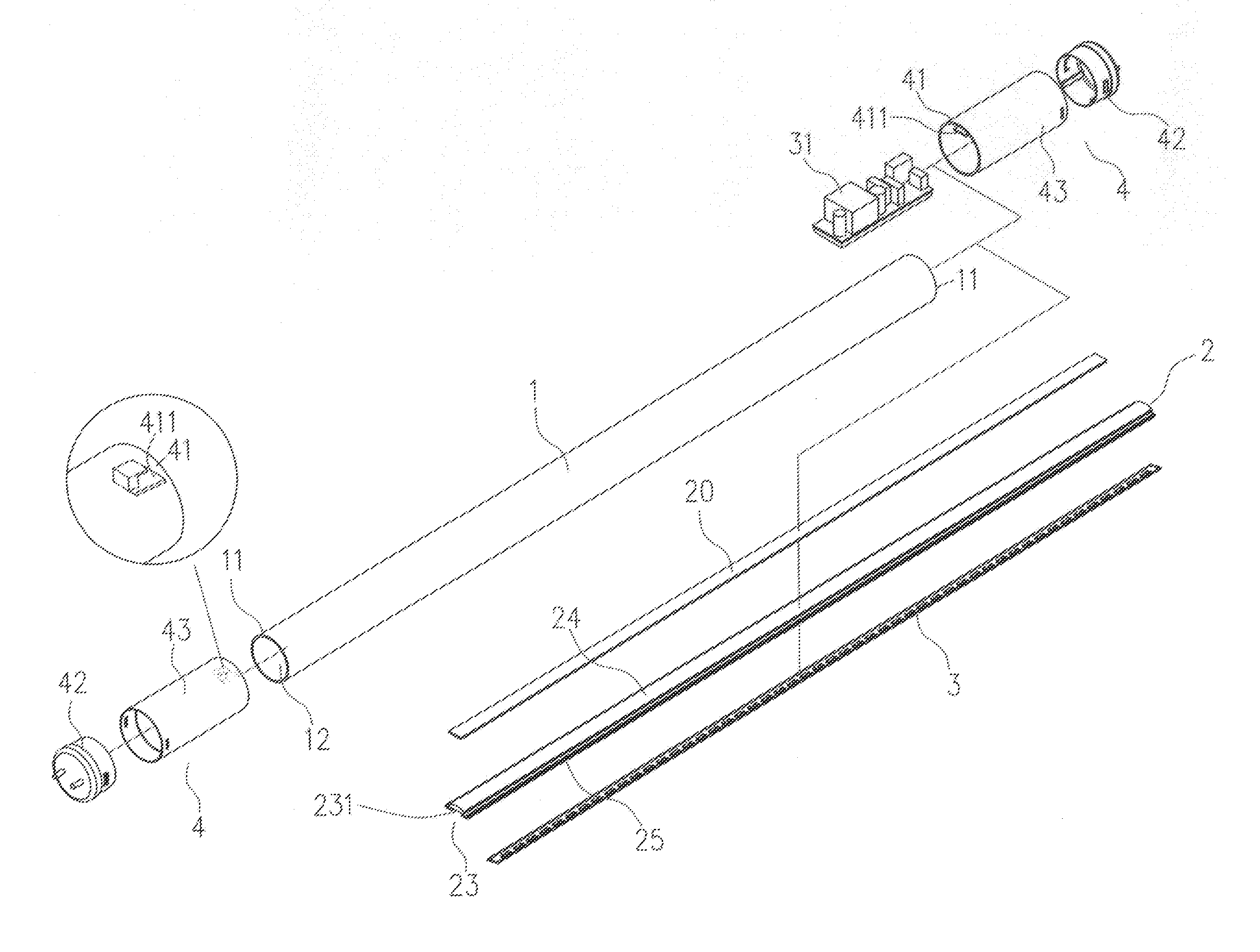
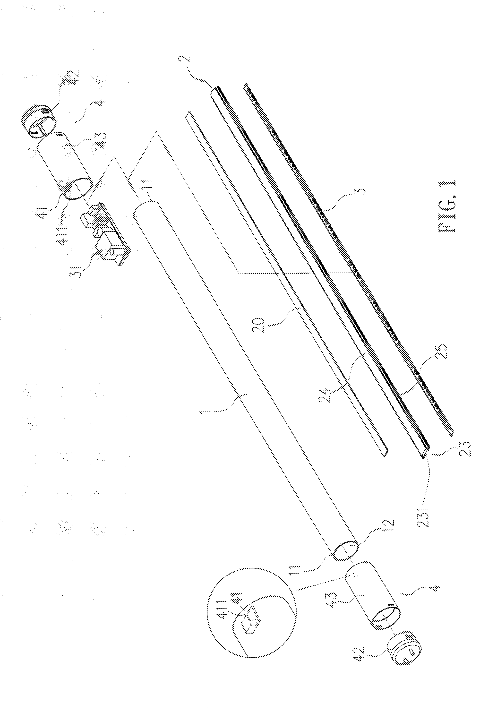
[0019]Please refer to FIGS. 1 to 3. An LED tube lamp structure according to a preferred embodiment of the present invention mainly includes a glass tube 1, a heat-dissipation metal base 2, an LED chip circuit board 3, and two electrode covers 4.

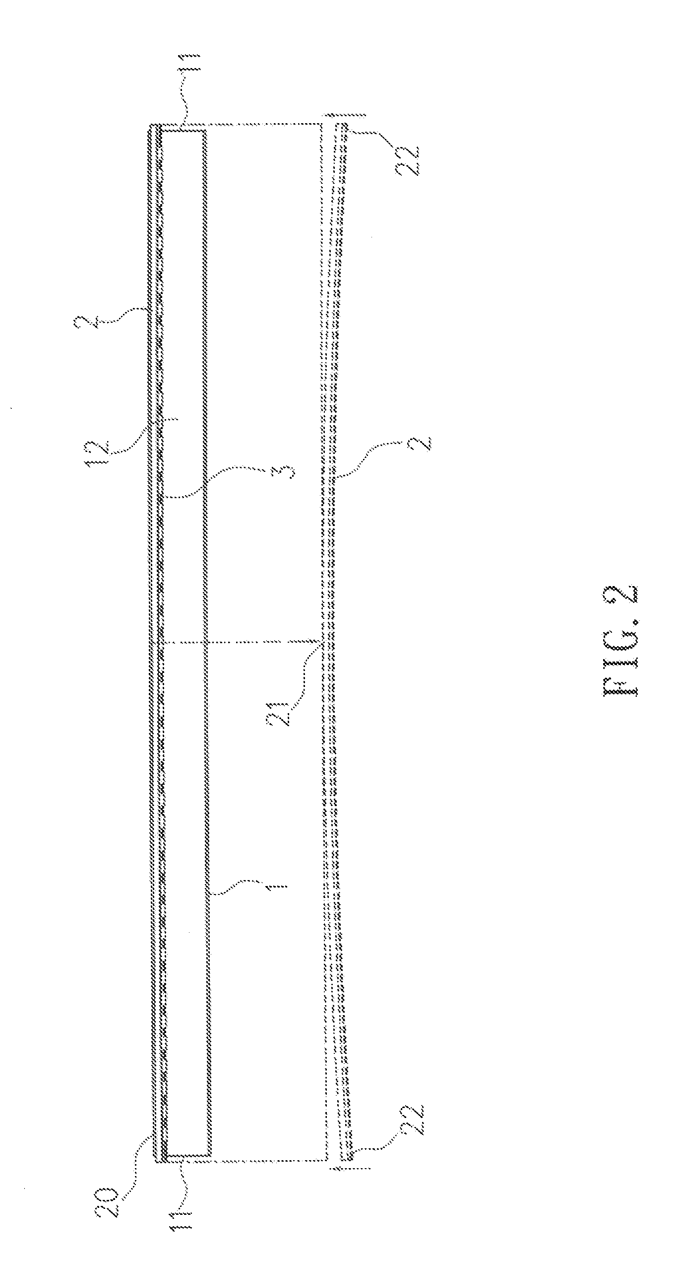
[0020]The glass tube 1 is a heat-transferring and light-pervious hollow cylindrical member having two open ends 11.

[0021]The heat-dissipation metal base 2 is an elongated strip having a slightly arched middle portion 21 located between two end portions 22, and therefore shows a certain degree of curve. The heat-dissipation metal base 2 includes a front side forming a receiving seat 23, a rear side for binding to an inner surface 12 of the glass tube 1 via a thermal adhesive 20. In practical implementation of the present invention, the heat-dissipation metal base 2 can be an elongated aluminum extrusion strip ha...


PUM


Abstract

An LED tube lamp structure includes a heat-transferring and light-pervious glass tube; a heat-dissipation metal base in the form of an elongated strip with a predetermined curve and bonded to an inner surface of the glass tube via a thermal adhesive; an LED chip circuit board fitted in a receiving seat on a front side of the heat-dissipation metal base and connected to an LED driving circuit; and two electrode covers fitted on two open ends of the glass tube and internally provided with an insertion section each. The heat-dissipation metal base has two ends inserted into the two insertion sections to have an upward tension for tightly contacting with the glass tube. Therefore, heat produced by the LED tube lamp is effectively transferred to the glass tube and dissipated into ambient air to extend the service life of the LED tube lamp.

Description

FIELD OF THE INVENTION[0001]The present invention relates to an LED tube lamp structure, and more particularly to an LED tube lamp structure that includes an elongated heat-dissipation metal base having a curved rear side attached to an inner surface of a heat-transferring and light-pervious glass tube via a thermal adhesive, so that the LED tube lamp not only provides high brightness, but also enables the heat produced by it to uniformly dissipate into ambient air via the glass tube.BACKGROUND OF THE INVENTION[0002]Currently, fluorescent lamps are requisite lighting means in people's daily life. However, thanks to the constant development in various technical fields, light-emitting diodes (LEDs) have been developed as new generation of lighting means. LEDs have many advantages, such as high brightness, fast response time, small volume, low power consumption, energy-saving, safe for use, and long service life. Therefore, LED lamps have been widely used in many applications to replac...

Claims


Application Information

Patent Timeline
IPC IPC(8): F21V29/00
CPCF21V29/506F21V29/70F21K9/27F21Y2115/10
Inventor WU, TAN CHIHYANG, FU PAO
Owner FIN CORE
Why Eureka
Try Eureka