Pneumatic Boat Lift with Boat-Carrying and Boat-Guiding Air Tanks

a technology of pneumatic boat lift and air tank, which is applied in the direction of waterborne vessels, dry-docking, slipways, etc., to achieve the effect of reducing the buoyancy of the air tank for movemen

Inactive Publication Date: 2014-01-09
DAVIS W JOHN
View PDF14 Cites 14 Cited by
  • Summary
  • Abstract
  • Description
  • Claims
  • Application Information

AI Technical Summary

Benefits of technology

[0044]an air release mechanism connected to each tank and operable to release air from within the hollow inte

Problems solved by technology

However, the forgoing floating lift designs have been developed for monohull (single-hulled) watercraft, and accordingly are not confi

Method used


Image

  • Pneumatic Boat Lift with Boat-Carrying and Boat-Guiding Air Tanks
  • Pneumatic Boat Lift with Boat-Carrying and Boat-Guiding Air Tanks
  • Pneumatic Boat Lift with Boat-Carrying and Boat-Guiding Air Tanks

Examples


Embodiment Construction

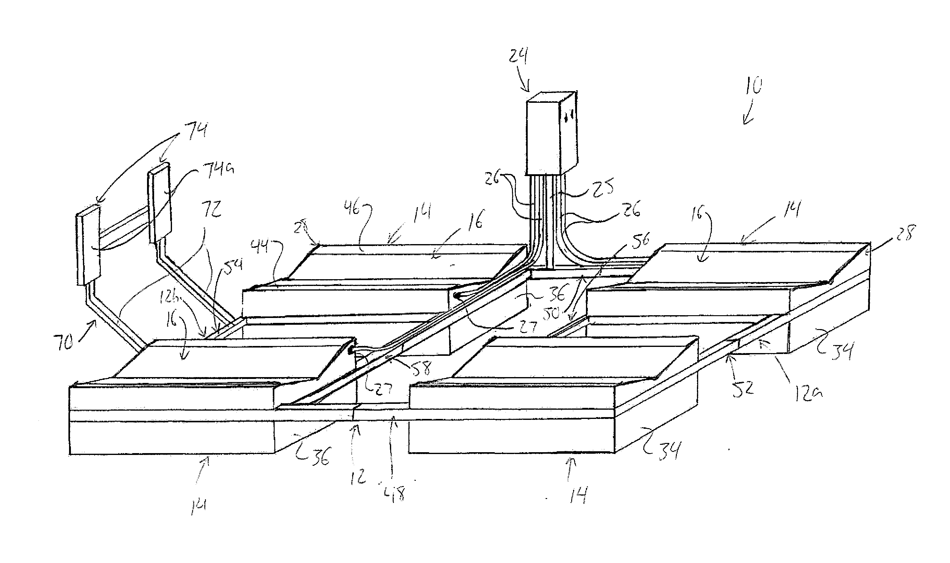
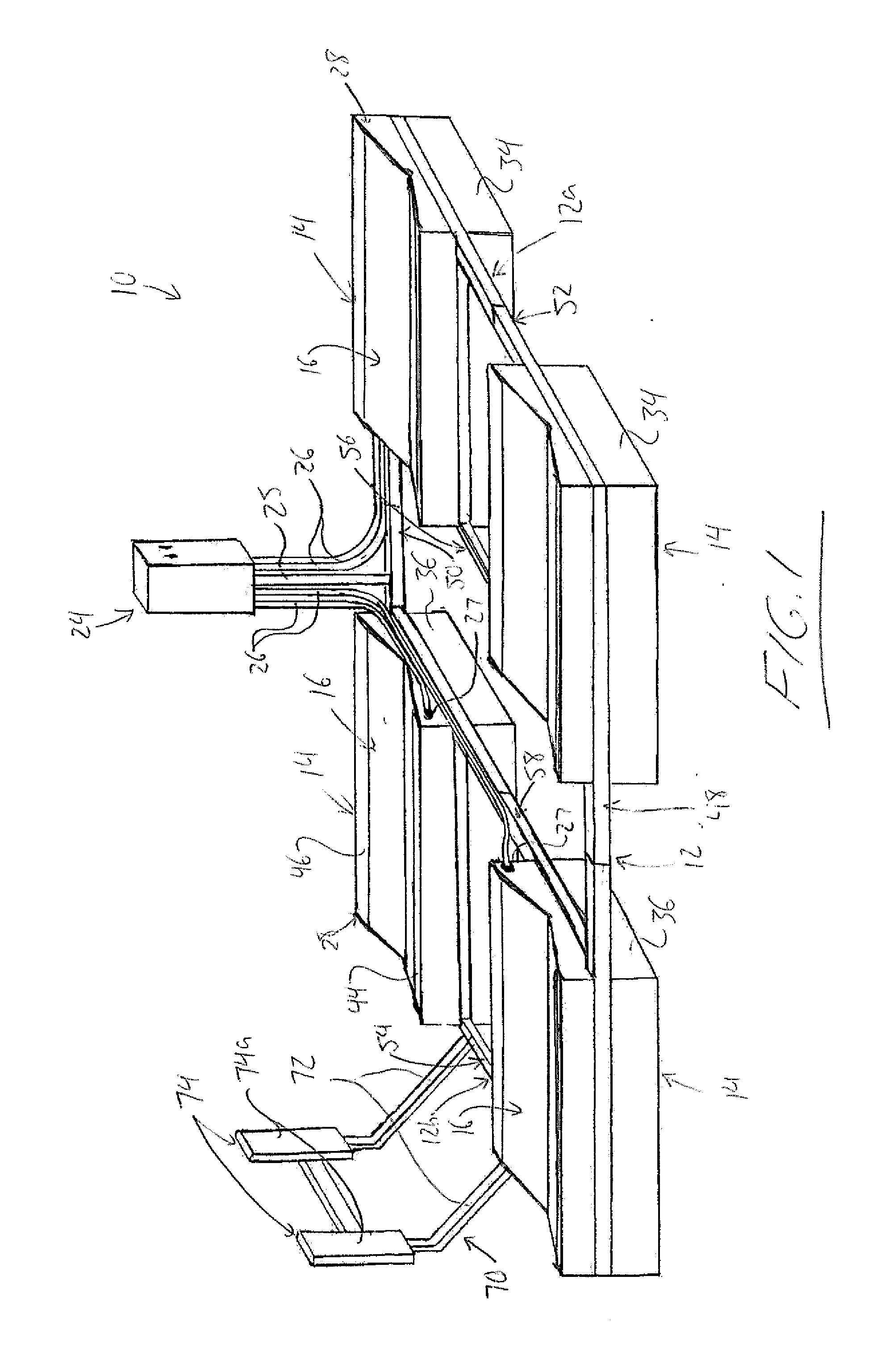
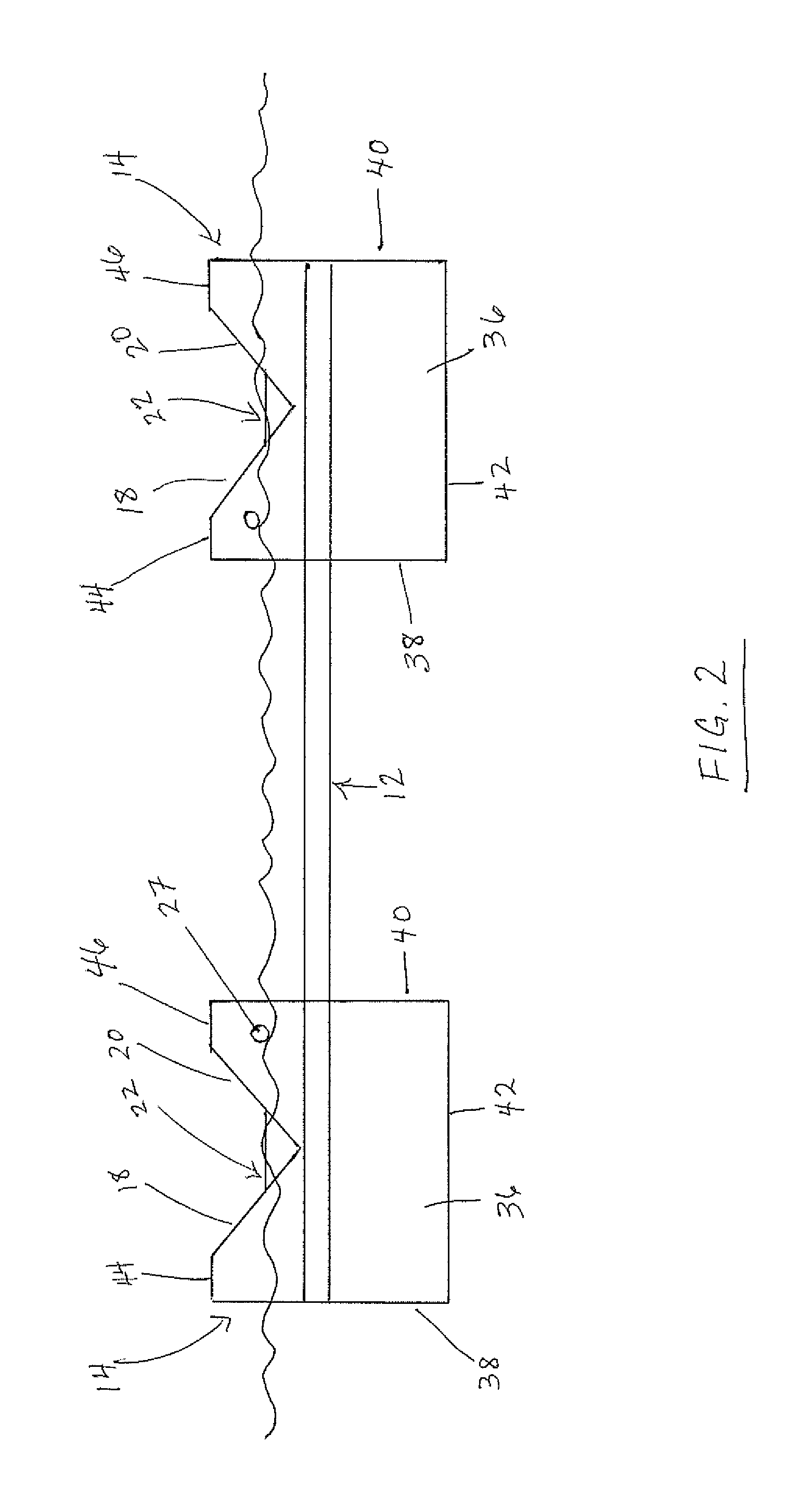
[0057]FIG. 1 shows a pontoon boat lift 10 of the present invention configured for selective raising and lowering of a pontoon boat out of and back into a lake, river, sea or other body of water. The boat lift 10 features a frame 12 defining a rectangular shape of the boat lift 10 in plan view, and four air tanks 14 each mounted to the frame 12 at a respective one of the four corners of its rectangular shape. Each tank 14 is a polyhedron in overall shape, featuring a concave upper end 16 having two sloped rectangular walls 18, 20 that join one another at their lower edges to define a V-shaped channel 22 between them. An outer one of the sloped wall angles upwardly and laterally outwardly toward the respective side of the frame, while the inner one angles upwardly and laterally inward toward the transverse center of the frame. A control housing 24 carried at a distance above the frame by an upright 25 mounted thereon contains an air pump therein, the output of which feeds the inlet of...


PUM


Abstract

A pontoon boat lift features tanks adjacent opposite sides thereof with upper walls slopes upwardly in a laterally outward direction. In lowered positions of the tanks, top ends of the sloped walls remain above water for visual and physical guidance of the pontoon boat into a position placing pontoons thereof between the outwardly sloped walls and over submerged portions of the lowered tanks, thereby allowing subsequent seating of the pontoons on said sloped walls during raising of the air tanks to lift the pontoons from the water. Buoyancy control for raising and lowering of the tank is effected by controlling air and water content thereof. The tanks are arranged to trap sufficient air therein to keep the lift buoyant to prevent sinking without using legs to support the boat lift on the sea, lake or river bed. The lift is adjustable in width and length for boats of varying size.

Description

FIELD OF THE INVENTION[0001]The present invention relates to a lift for raising a pontoon boat out of a body of water, and more particularly to such a lift that employs floating air tanks on which the boat is directly supported when the lift is raised.BACKGROUND OF THE INVENTION[0002]In the field of watercraft, it is sometimes desirable to store a watercraft in an elevated position over a body of water, for example to avoid the hassle of repeatedly launching a boat into the body from shore while also avoiding complications that can arise from keeping the boat in the water when out of use. Accordingly, several boat lift designs have been previously proposed.[0003]Many prior art boat lifts are mechanical in design, for example employing a bulky structure having a base frame that carries a movable section for lifting the boat, for example through operation of a winch. Other boat lifts employ buoyancy based designs, where the lifting action is instead provided by pontoons or inflatable ...

Claims


Application Information

Patent Timeline
IPC IPC(8): B63C3/06
CPCB63C1/06
Inventor DAVIS, W. JOHN
Owner DAVIS W JOHN
Why Eureka
Try Eureka