Supercharge Your Innovation With Domain-Expert AI Agents!

LED light source

a technology of led light source and led load, which is applied in the direction of light source, electrical apparatus, lighting apparatus, etc., to achieve the effect of increasing the total current supplied to led loads

Active Publication Date: 2014-01-16
KONINKLIJKE PHILIPS ELECTRONICS NV
View PDF4 Cites 6 Cited by
  • Summary
  • Abstract
  • Description
  • Claims
  • Application Information

AI Technical Summary

Benefits of technology

The LED light source described in this patent has a unique design that allows the LED loads to carry the same average current during each step of the low-frequency AC supply voltage. This results in higher LED utilization and cheaper LED packages. The control of the switches is simple and dependable, and the second control circuit ensures that the LED loads are always optimally supplied with current. Overall, this LED light source has improved performance and cost-effectiveness.

Problems solved by technology

However, most of the LED packages used in the LED light source are not used in the first LED load.

Method used


Image

  • LED light source
  • LED light source
  • LED light source

Examples


Embodiment Construction

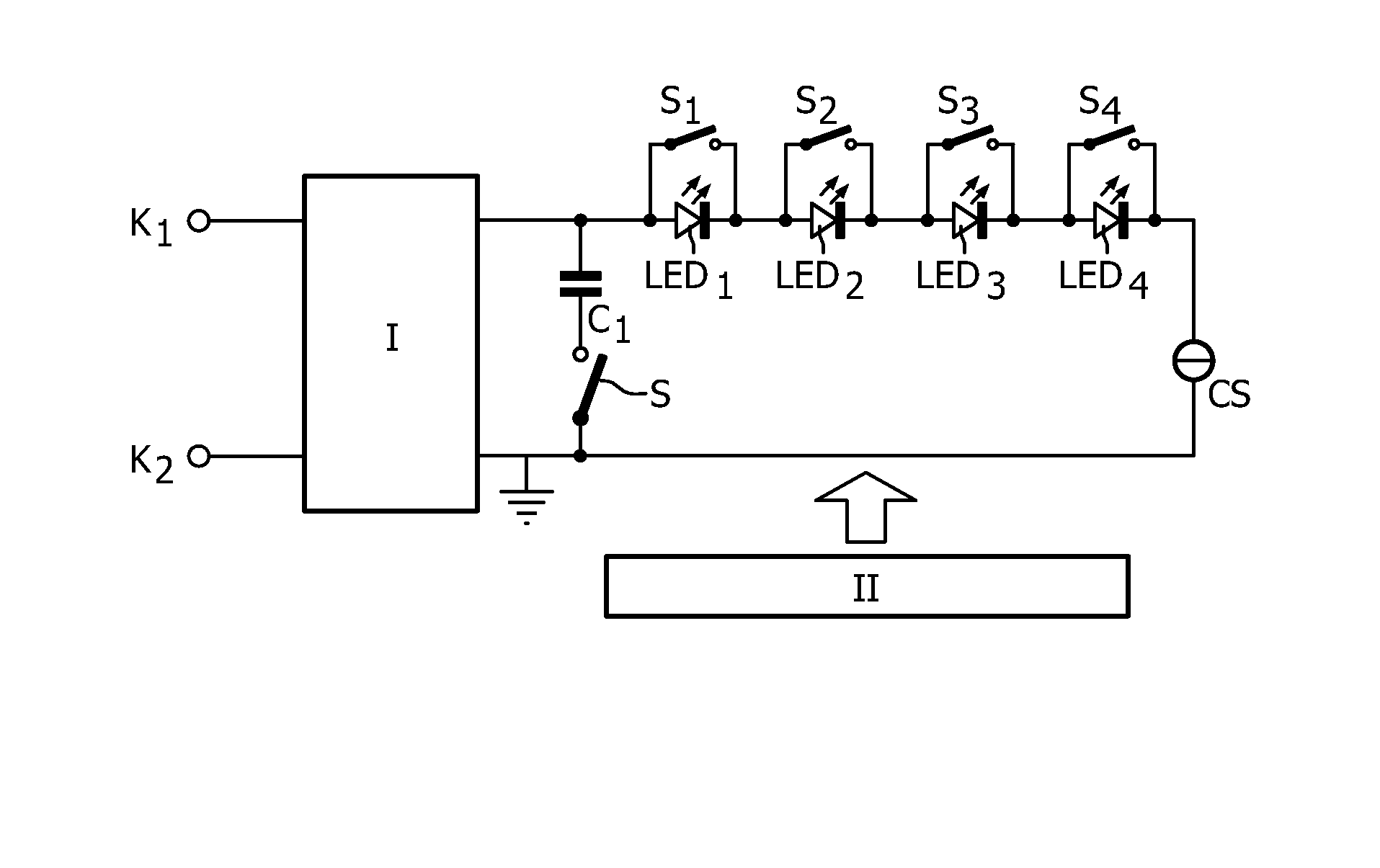
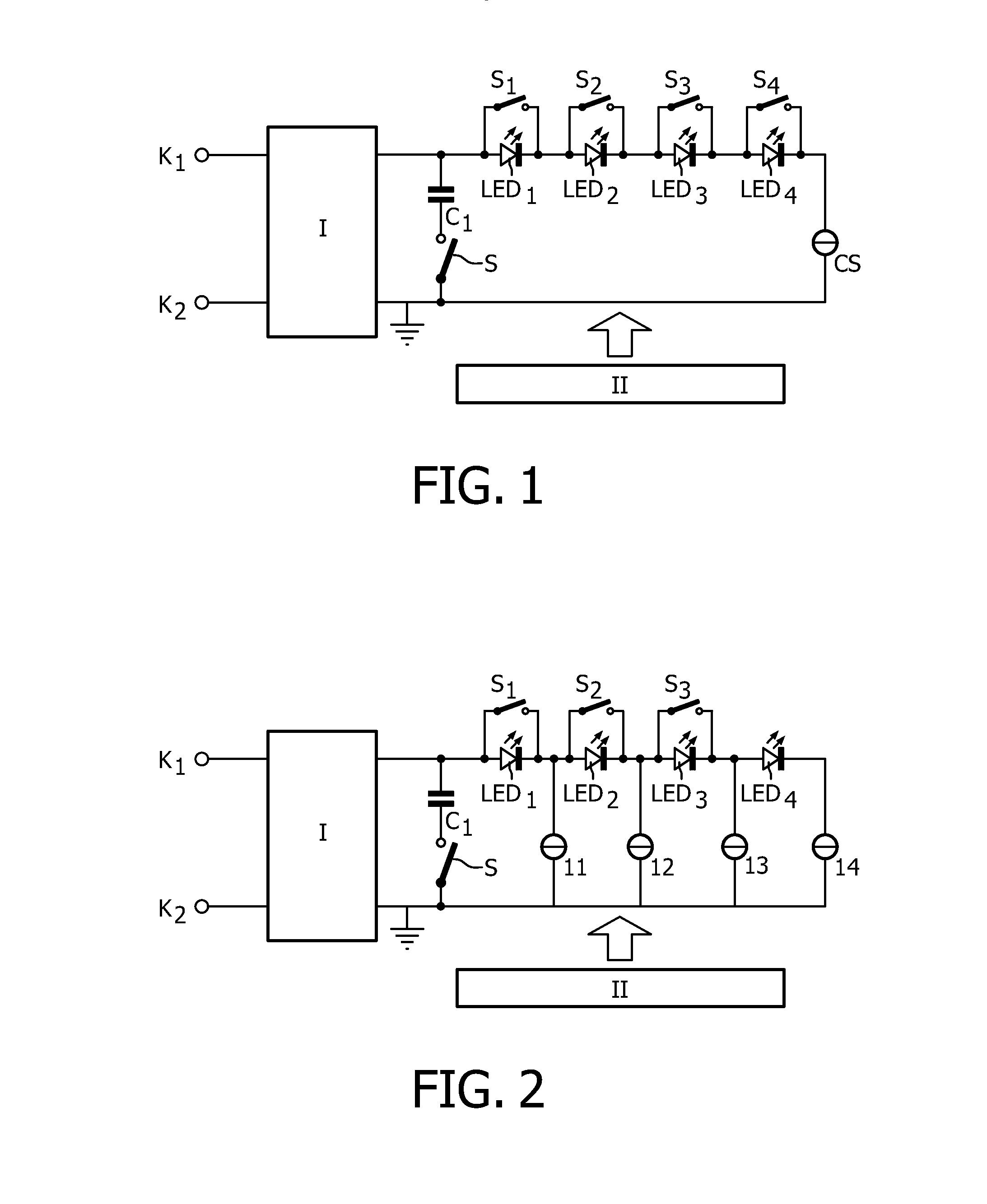
[0051]In FIG. 1, K1 and K2 are first and second input terminals, respectively, for connection to a low-frequency supply voltage source, such as the European or American mains supply.

[0052]Reference I is a rectifier coupled to the input terminals for rectifying the low-frequency AC supply voltage. Output terminals of the rectifier are connected by means of a series arrangement of a capacitive element C1 and a switch S. The output terminals are also connected by a series arrangement of four LED loads LED1-LED4 and a current source CS. Each of the LED loads is shunted by a control string comprising a switch. These switches are labeled S1 to S4. Reference II is a control circuit for controlling the switches S1-S4 and also switch S. Switches S1-S4, current source CS and the control circuit II together form control means.

[0053]It is noted that it is possible to connect the output terminals of the rectifier by means of a bleeder to make the LED light source compatible with a phase-cut dimm...


PUM


Abstract

LED light source comprising a string of LED loads (LED1-LED4) supplied by a rectified mains voltage. The number of LED loads carrying current is increased as the momentary amplitude of the rectified mains voltage increases, and is decreased as the momentary amplitude of the rectified mains voltage decreases. The order in which the LED loads start carrying a current and the order in which the LED loads stop carrying a current is reversed for each half period of the mains.

Description

FIELD OF THE INVENTION[0001]The invention relates to an inexpensive and simple LED light source comprising N LED loads that is directly connectable to a supply source supplying a low-frequency AC voltage, such as the mains supply.BACKGROUND OF THE INVENTION[0002]Such a LED light source is known from U.S. Pat. No. 7,081,722. The LED loads are LED arrays comprising series arrangements and possibly parallel arrangements of individual LEDs. During operation, a periodic DC voltage with a frequency 2f and an amplitude varying between zero Volt and a maximum amplitude is present between the output terminals of the rectifier. When the amplitude of the periodic DC voltage is zero Volt, none of the LED loads carries current. When the amplitude of the periodic DC voltage increases, a voltage is reached at which the first LED load starts carrying current. Similarly, when the amplitude of the periodic DC voltage increases further to a high enough value, the second LED load starts conducting.[000...

Claims


Application Information

Patent Timeline
Patent Type & Authority Applications(United States)
IPC IPC(8): H05B33/08H05B44/00
CPCH05B33/083H05B45/48
Inventor TAO, HAIMINCREUSEN, MARINUS PETRUSKURT, RALPH
Owner KONINKLIJKE PHILIPS ELECTRONICS NV
Features
  • R&D
  • Intellectual Property
  • Life Sciences
  • Materials
  • Tech Scout
  • Unparalleled Data Quality
  • Higher Quality Content
  • 60% Fewer Hallucinations
Learn More