Progressive power lens, method of designing progressive power lens and method of evaluating progressive power lens

a technology of progressive power lens and lens body, applied in the field of progressive power lens, can solve the problems of wearer distortion or sway of images, and it is difficult to design progressive power lens, and achieve the effect of less likely to impede binocular vision

Active Publication Date: 2014-01-16
HOYA CORP
View PDF0 Cites 3 Cited by
  • Summary
  • Abstract
  • Description
  • Claims
  • Application Information

AI Technical Summary

Benefits of technology

[0030]With the progressive addition lens and the design method thereof according to the present invention, by individually considering the design principal meridian curve and the principal line of vision when the wearer actually moves the line-of-sight, it is possible to design the progressive addition lens so as to obtain an amount of inward movement of line-of-sight as intended as designed. To be specific, by setting an amount of design inward movement which is greater than the amount of inward movement of line-of-sight intended when designing, it is possible to obtain an amount of inward movement of line-of-sight as intended as designed, and therefore it is possible to provide spectacles which are less likely to impede binocular vision.
[0020]Further, it is another object of the present invention to suitably evaluate the progressive addition lens by considering the influence of the measuring device such as the lens meter or the like.

Problems solved by technology

However, it is difficult to design a progressive addition lens because it is necessary to arrange a plurality of visual fields within a limited lens area without interposing a boundary between the plurality of visual fields, the plurality of visual fields being: a visual field for viewing far distance, a visual field for viewing near distance, and a visual field for viewing medium distance.
For this reason, it is widely known that the progressive addition lens has its particular disadvantages such as that each visual field is not always sufficiently wide, and that there is a region mainly in a side visual field which causes the wearer to feel distortion or sway of an image.
However, most of these prior arts are related to design technique for obtaining more preferred power distribution or astigmatism distribution depending on individual prescribed power and wear state, and relatively few of these prior arts are made to improve binocular vision of right and left eyes (see Patent Document 1 to 4).

Method used


Image

  • Progressive power lens, method of designing progressive power lens and method of evaluating progressive power lens
  • Progressive power lens, method of designing progressive power lens and method of evaluating progressive power lens
  • Progressive power lens, method of designing progressive power lens and method of evaluating progressive power lens

Examples


embodiment

[2] Embodiment of Evaluation Method for Progressive Addition Lens

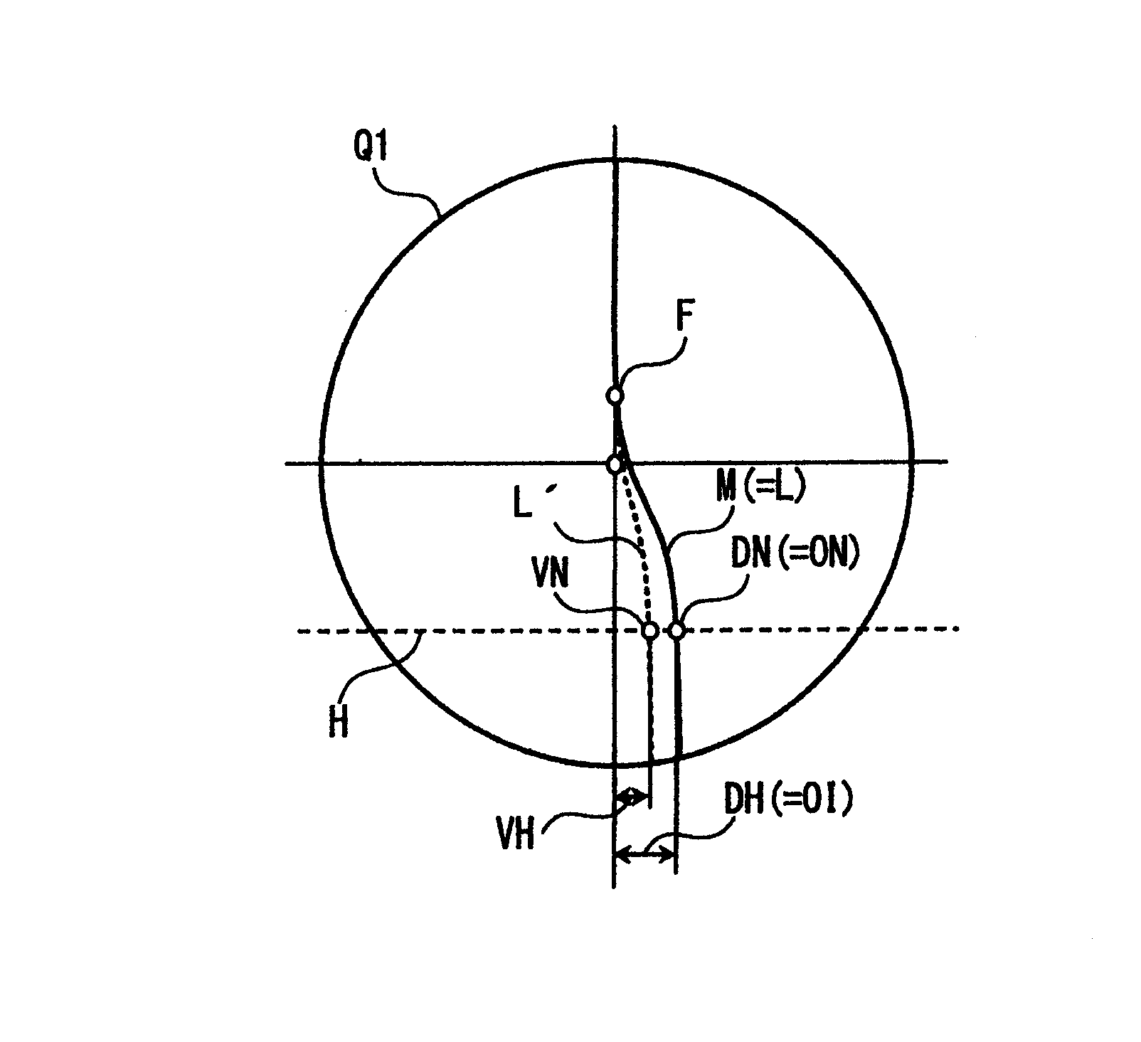
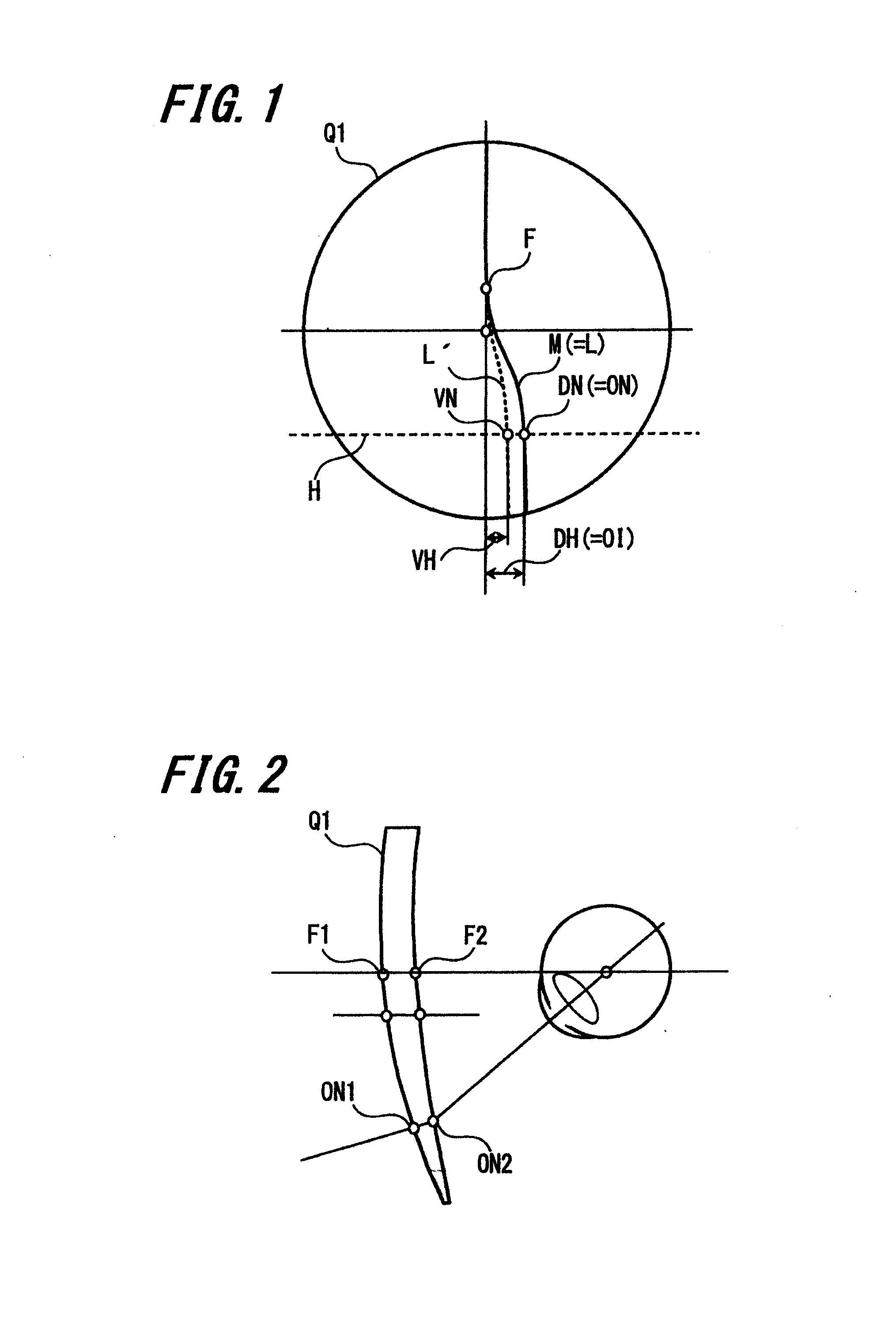
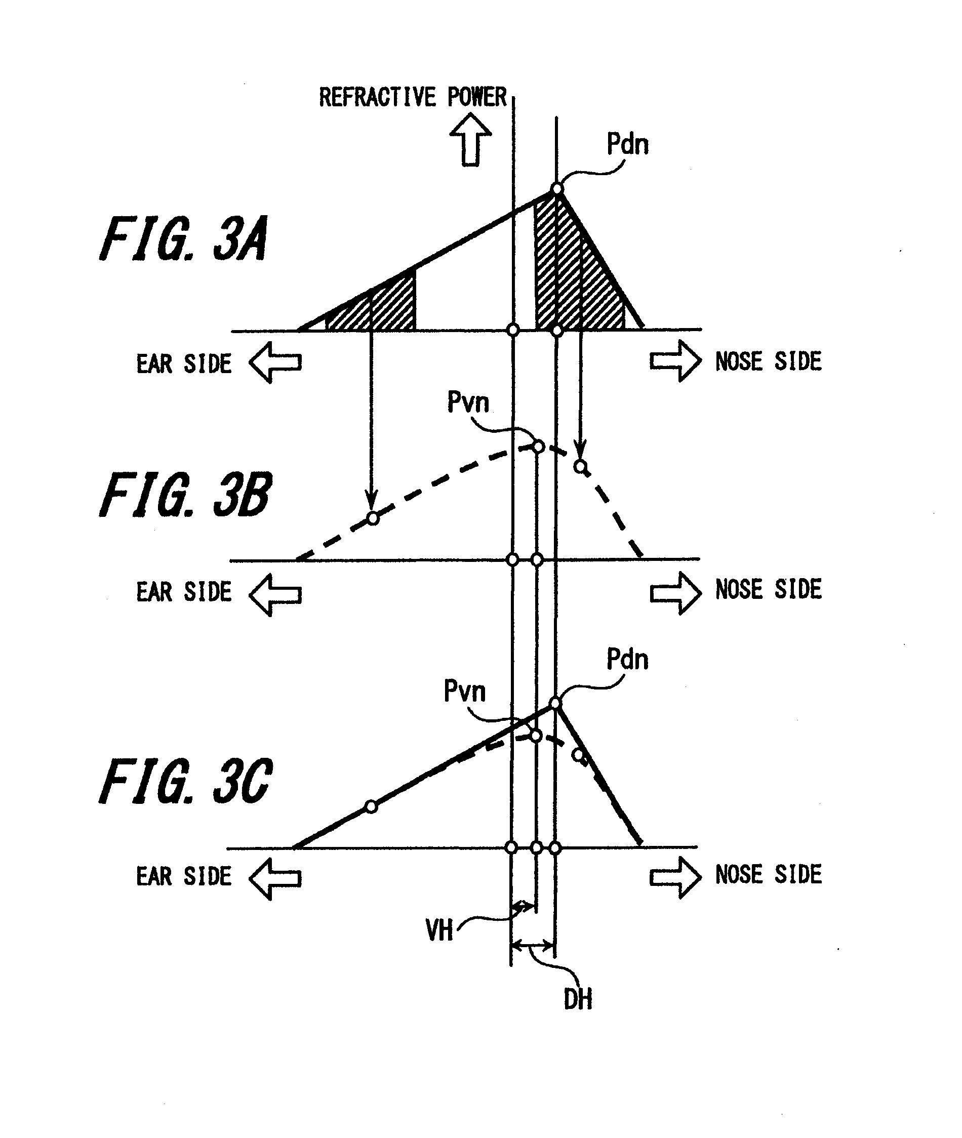
[0104]Next, an embodiment of evaluation method for progressive addition lens according to the present invention will be described below. The evaluation of the optical characteristics (such as power, refractive power distribution state, layout position and the like) of the progressive addition lens is performed after the lens is designed and then trial-produced according to the design. To be specific, as the flow of a typical production process of the progressive addition lens, the lens is designed first. In the designing step, when determining the arrangement of the design principal meridian curve, the amount of inward movement is determined and laid out on the lens.

[0105]Further, while the processing is transferred from the designing step to the production step, there is a trial production step in which it is necessary to verify whether or not the production of the lens is performed according to the design. The verifi...


PUM


Abstract

Improving the optical state of a progressive addition lens along a principal line of vision through which the line-of-sight of a wearer passes by making the displacement of a position at which an optical state becomes the best to be the same as the amount of inward movement of line-of-sight, when the wearer moves his line-of-sight from the front far distance to the front near distance. An expression OI<DH may be satisfied to improve such an optical state of the progressive addition lens.

Description

[0001]The present application is a divisional application of U.S. patent application Ser. No. 12 / 920,784, filed on Sep. 2, 2010, which is in turn a National Stage entry of PCT / JP2009 / 066954, filed Sep. 29, 2009, the disclosures of all of which are hereby incorporated by reference.TECHNICAL FIELD[0002]The present invention relates to a progressive-power lens (progressive addition lens) in which pupil diameter is taken into consideration, which is a kind of multifocal spectacle lens having addition power for compensating for insufficient accommodation ability caused by presbyopia, a method of designing the progressive addition lens, and a method of evaluating the progressive addition lens.BACKGROUND ART[0003]A progressive addition lens is widely used in general due to its advantages such as that it is not easily recognized as a presbyopia spectacle lens from appearance although it actually is, and that it allows a wearer to clearly look continuously from a far distance to a near dista...

Claims


Application Information

Patent Timeline
Patent Type & Authority Applications(United States)
IPC IPC(8): G01M11/02
CPCG01M11/0207G01M11/0228G02C7/061G02C7/065G02C7/027
Inventor KITANI, AKIRA
Owner HOYA CORP
Why Eureka
Try Eureka