
Additional Knurled Ring for Optical Lens

a technology of optical lenses and knurled rings, which is applied in the direction of printers, camera filters, camera focusing arrangements, etc., can solve the problems of not being able to incorporate optical adjusting assistance equipment, dramatically affecting the quality of images,

Inactive Publication Date: 2014-01-16
SHENZHEN PCHOOD TECH
View PDF18 Cites 9 Cited by
  • Summary
  • Abstract
  • Description
  • Claims
  • Application Information

AI Technical Summary

Benefits of technology

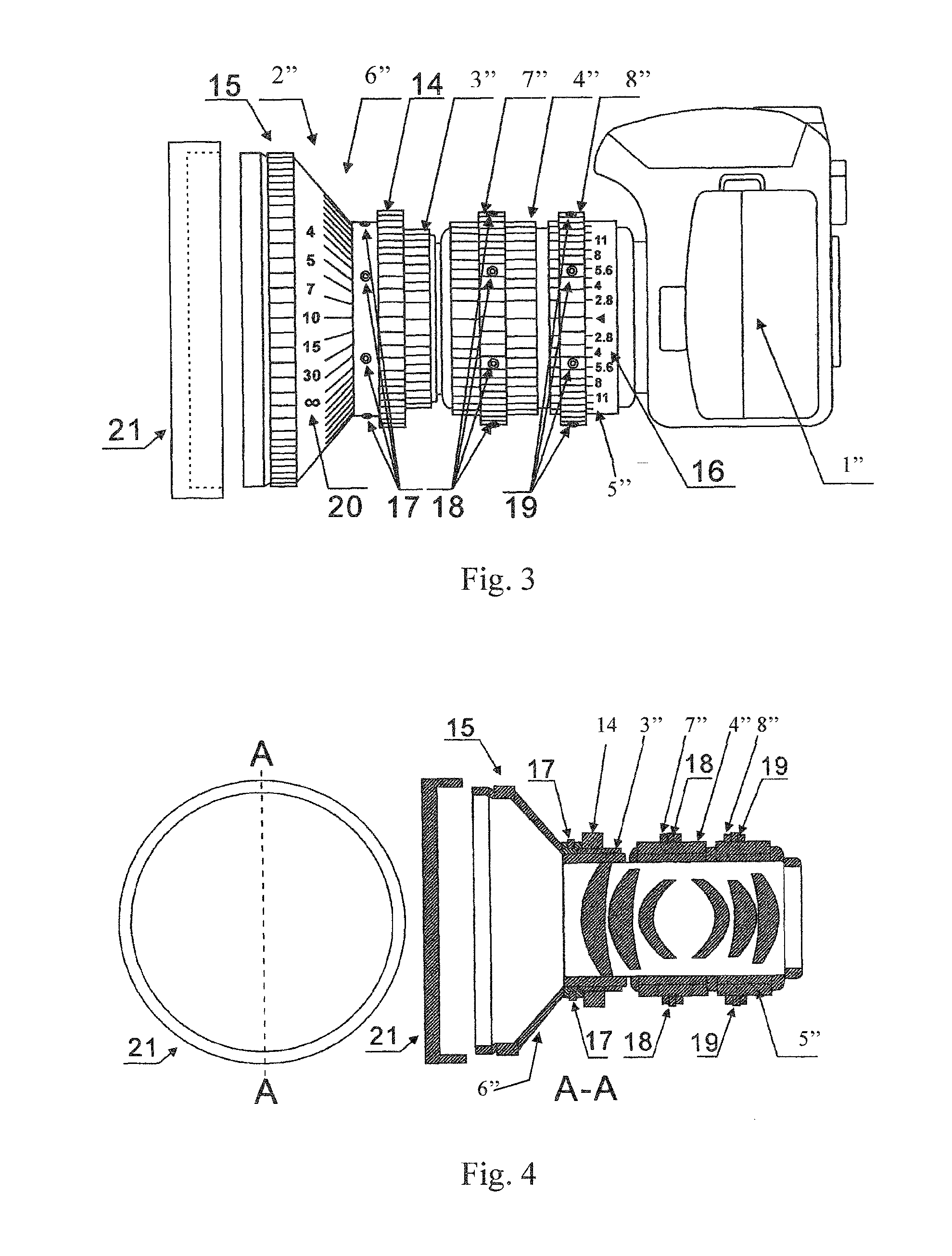
The present invention provides an additional knurled ring for an optical lens that can help overcome issues like image shake, focus retardation, and noise generation. It can also extend and enlarge towards the front of the optical lens to prevent interference from stray light. Additionally, a movable cap is connected to the front and enlarged end of the additional knurled ring for protection. The diameter and shape of the cap match with the diameter and shape of the front and enlarged end of the additional knurled ring of the optical lens.

Problems solved by technology

Nowadays, a conventional optical camera doesn't not include a knurled ring, so that it cannot be incorporated with optical adjusting assistance equipment which are a follow focus of the file lens and a converter.
In particular, while the digital conventional optical camera is utilized for shooting, the image shake, focus retardation, and noise generation from autofocus are common problems for the digital conventional optical camera so as to dramatically affect the quality of the images.

Method used


Image

  • Additional Knurled Ring for Optical Lens
  • Additional Knurled Ring for Optical Lens
  • Additional Knurled Ring for Optical Lens

Examples


Embodiment Construction

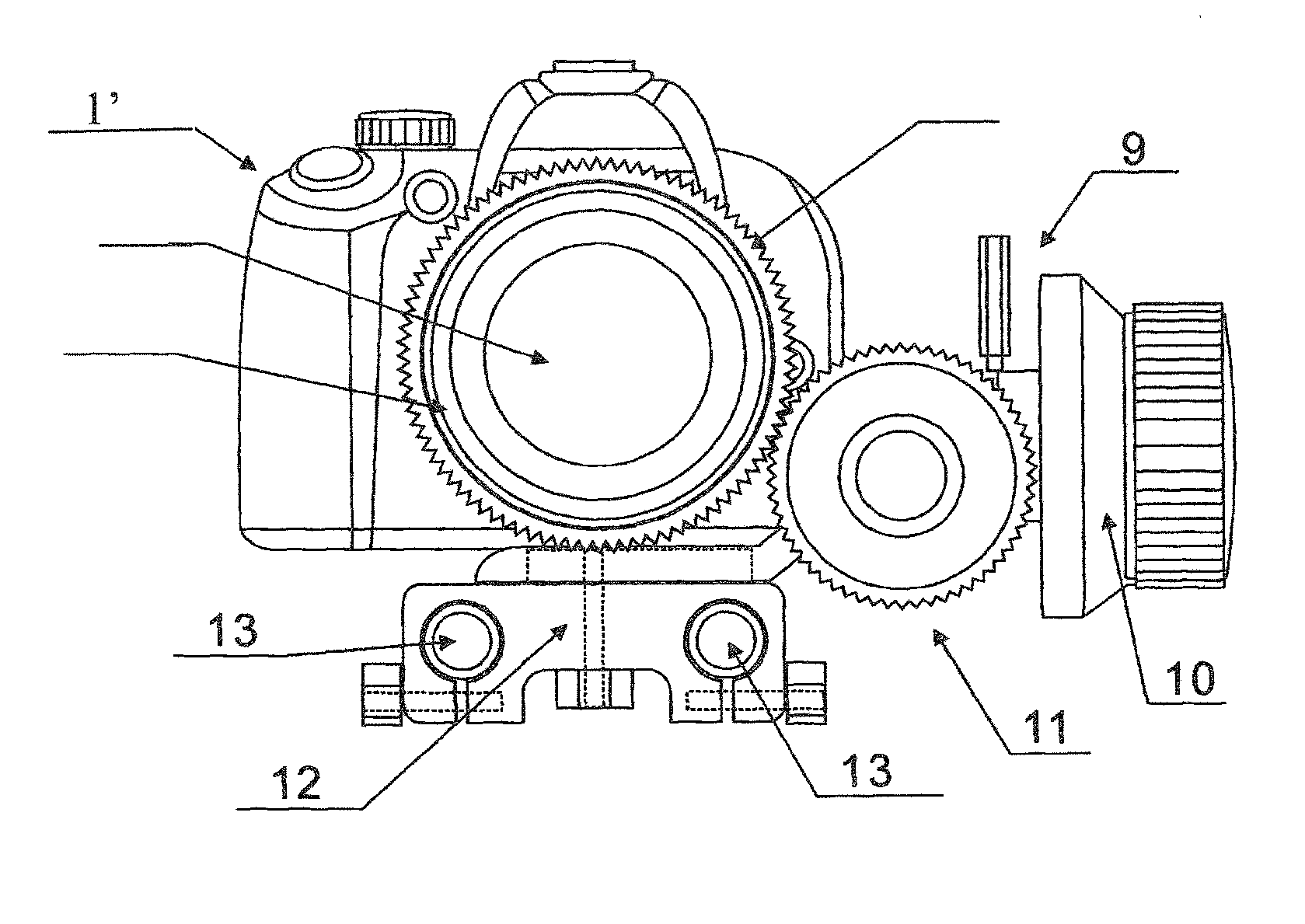
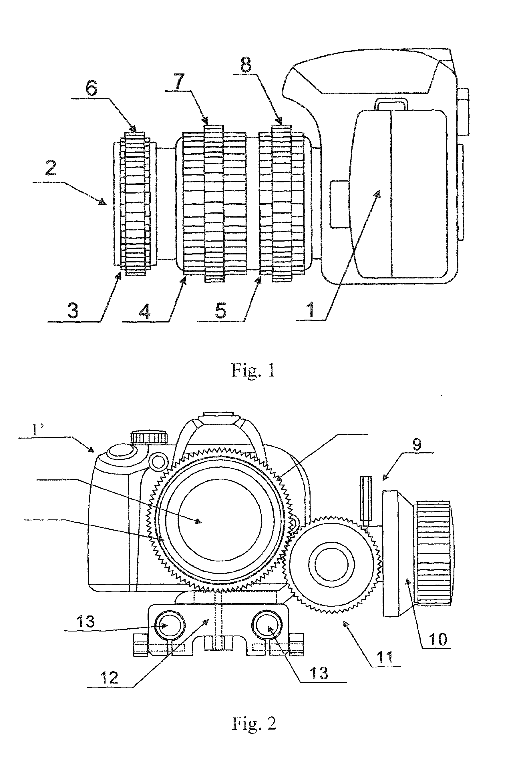
[0028]Referring to FIG. 1 of the drawings, an additional knurled ring for an optical lens according to a first preferred embodiment of the present invention is illustrated, wherein a camera comprises a camera body 1 connected to optical lens 2, at least one of additional knurled rings that is shown herein as a first additional knurled ring 6, a second additional knurled ring 7, and a third additional knurled ring 8, and at least one of the optical adjusting rings that is a focal length adjusting ring 3, a zoom ring 4, and a aperture adjusting ring 5, wherein the first additional knurled ring 6 is movably connected with the outside of the focal length adjusting ring 3, wherein the second additional knurled ring 7 is movably connected with the outside of the zoom ring 4, and the third additional knurled ring 8 is movably connected with the outside of the aperture adjusting ring 5. The inner diameter and shape of the first additional ring 6 match the outer diameter and shape of the foc...


PUM


Abstract

An additional knurled ring for an optical lens is composed of an annular portion and teeth distributed in a radial direction around the outside of the annular portion. The inner diameter and shape of the additional knurled ring match the outer diameter and shape of an adjusting ring of the optical lens. The additional knurled ring is movably connected with the outside of the adjusting ring of the optical lens. Since the additional knurled ring for the optical lens can be extended towards the front of the lens and beyond the front end of the optical lens, the interference of stray light with the imaging of the optical lens is blocked. Digital scale designations are engraved or printed on the outside of the additional knurled ring for optical lens, the position of the scale and the values of the designations are corresponding to the focal length, aperture, and focal range information of the optical lens. The front end with the enlarged outside diameter of the additional knurled ring for optical lens is movably connected with a cap, and the shape and size of the cap matches the shape and size of the front end of the additional knurled ring.

Description

NOTICE OF COPYRIGHT[0001]A portion of the disclosure of this patent document contains material which is subject to copyright protection. The copyright owner has no objection to any reproduction by anyone of the patent disclosure, as it appears in the United States Patent and Trademark Office patent files or records, but otherwise reserves all copyright rights whatsoever.BACKGROUND OF THE PRESENT INVENTION[0002]1. Field of Invention[0003]The present invention relates to an additional knurled ring, and more particular to an additional knurled ring for optical lens adapted for incorporated with different kinds of optical adjusting rings.[0004]2. Description of Related Arts[0005]Nowadays, a conventional optical camera doesn't not include a knurled ring, so that it cannot be incorporated with optical adjusting assistance equipment which are a follow focus of the file lens and a converter. Therefore, the conventional optical camera has the capability and equipment for utilizing manual foc...

Claims


Application Information

Patent Timeline
IPC IPC(8): G03B17/56
CPCG03B17/568G02B7/026G02B7/04G03B13/32G03B17/566G02B7/10G03B17/56
Inventor LUO, JIN
Owner SHENZHEN PCHOOD TECH
Learn More