Method of producing optical element, and optical element

A technology of optical components and manufacturing methods, applied in the direction of optical components, optical components, optics, etc., can solve problems such as imperfection and light loss

Inactive Publication Date: 2008-05-28
SANKYO SEIKI MFG CO LTD
View PDF1 Cites 10 Cited by
  • Summary
  • Abstract
  • Description
  • Claims
  • Application Information

AI Technical Summary

Problems solved by technology

If such a shape is a normal mechanical part, even if it does not become a big problem, it is not ideal when it is an optical element because the light incident on the boundary portion 22 will be lost.

Method used


Image

  • Method of producing optical element, and optical element
  • Method of producing optical element, and optical element
  • Method of producing optical element, and optical element

Examples


Embodiment Construction

[0062] Embodiments of the present invention will be described with reference to the drawings.

[0063] [Embodiment 1]

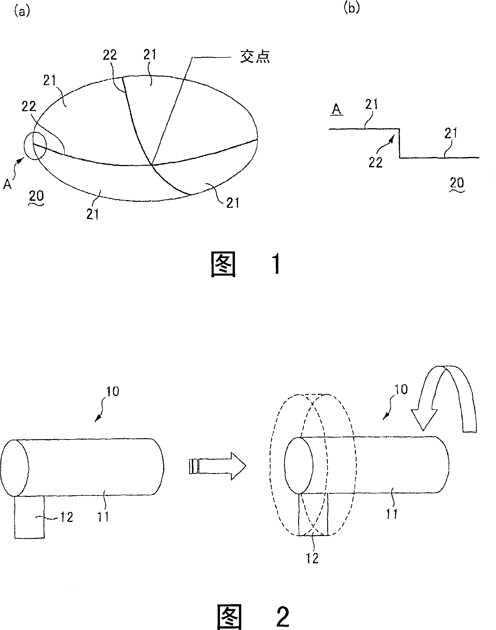
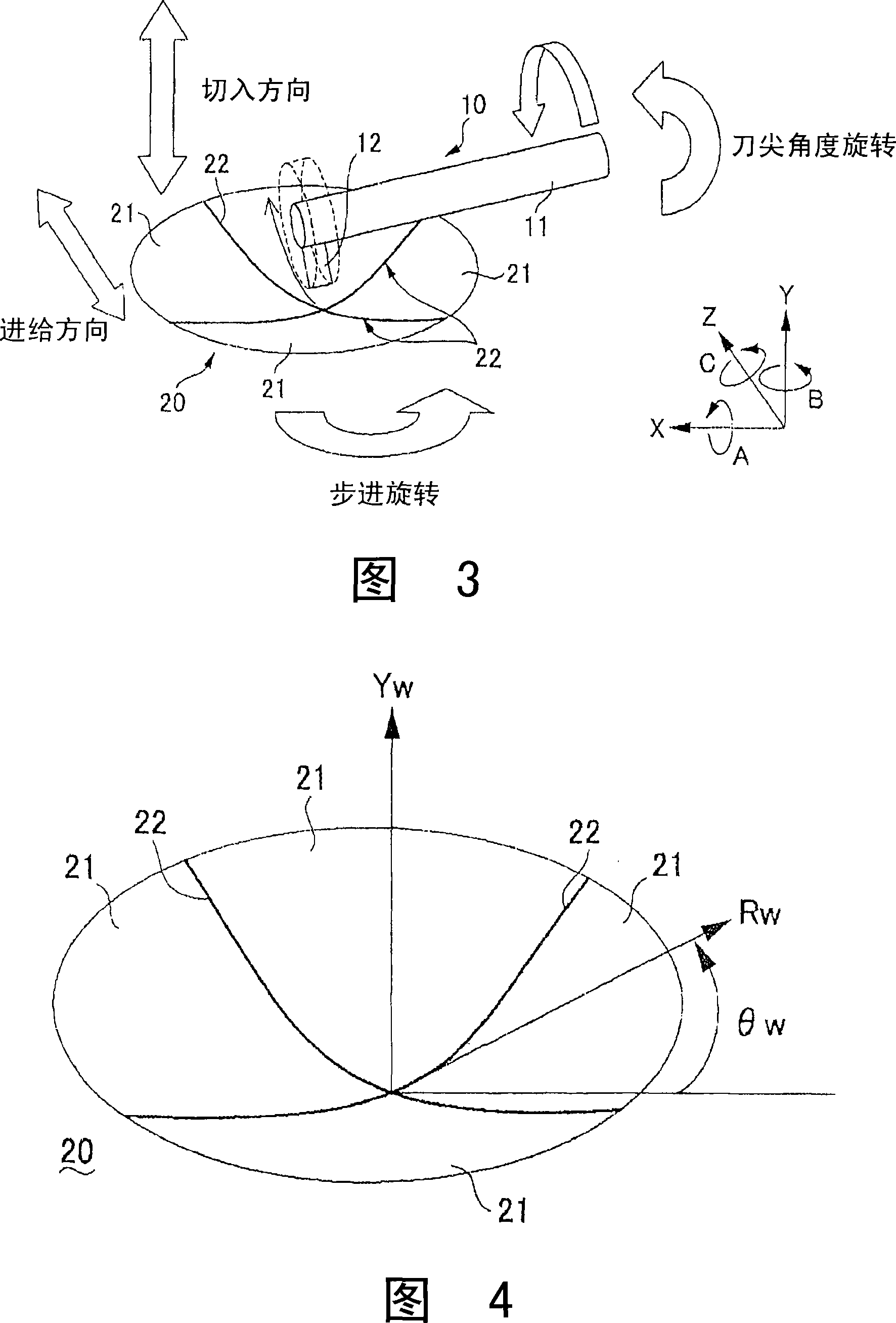
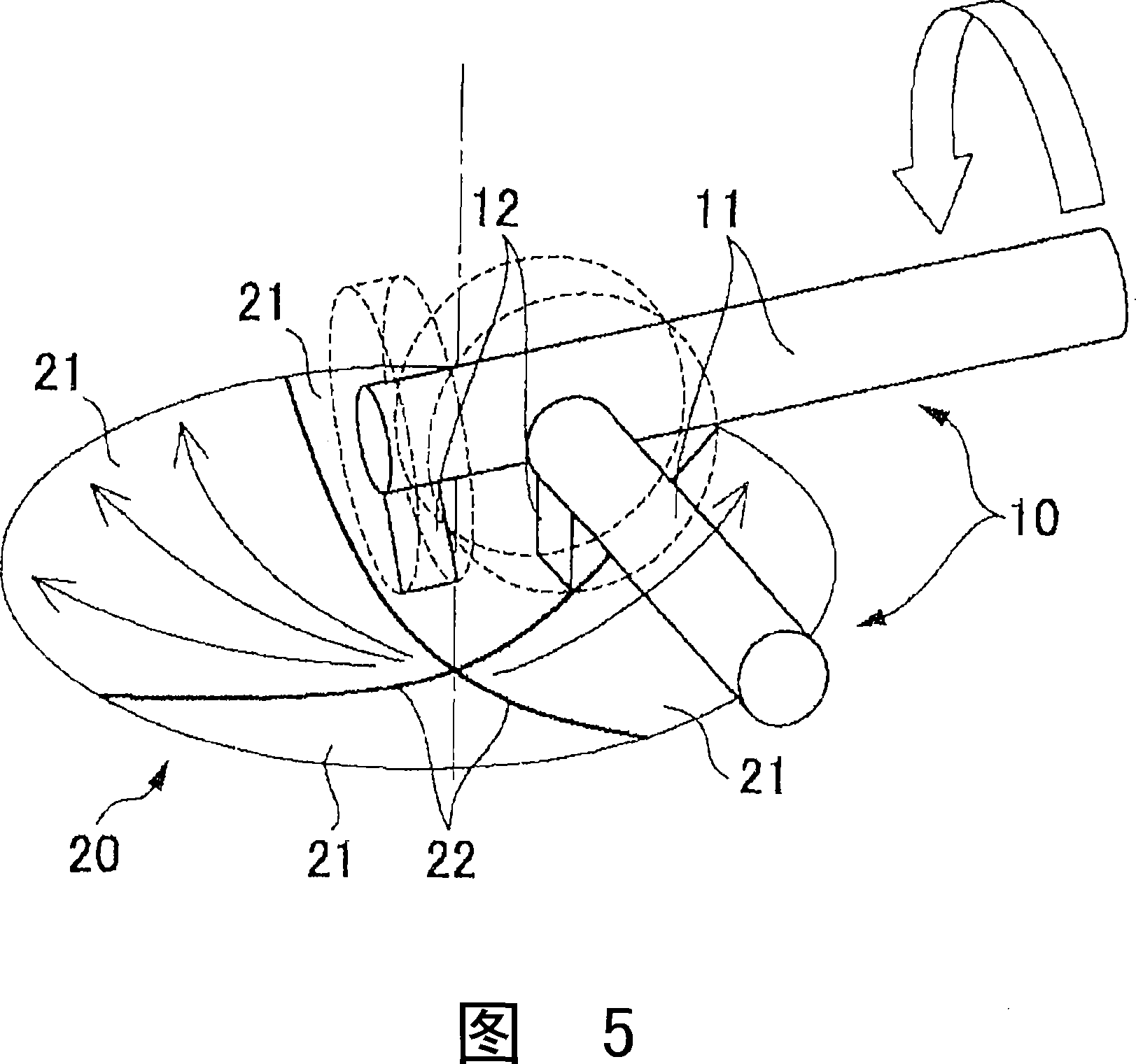
[0064] 1( a ) and ( b ) are explanatory views of an optical element according to the present invention and cross-sectional views of steps formed in the boundary region between the processed surfaces (element surfaces) of the optical element, respectively. Fig. 2 is an explanatory diagram of a flat flying knife. Fig. 3 is an explanatory view showing a processing method (manufacturing method of an optical element) according to Embodiment 1 of the present invention. Fig. 4 is an explanatory diagram of a cylindrical coordinate system used in the machining method of the present embodiment. Fig. 5 is an explanatory view at the time of processing a boundary portion in the processing method of the present embodiment. Fig. 6 is a cross-sectional view showing processing by the method shown in Fig. 5 .

[0065] In this embodiment, a flying knife protruding from the ...


PUM


Abstract

A fly cutter (10) having a rotating shaft (11) and a blade (12) projecting in the direction crossing the axis of the rotating shaft (11) is rotated about the axis of the rotating shaft (11). The fly cutter (10) being rotated and a base material (20) for forming an optical element are moved relative to each other in a cutting direction and a feeding direction to form worked surfaces (21) for forming an element surface. Out of two worked surfaces (21) adjacent, along a boundary (22) between worked surfaces (21), in the direction orthogonal to the rotating shaft (11), a lower side worked surface (21) is cut. The method can form a step at the boundary (22) between the two adjacent worked surfaces (21) when an optical element or a die is produced by cutting.

Description

technical field [0001] The present invention relates to a method of manufacturing an optical element by cutting or grinding a substrate for forming an optical element, such as an optical material constituting an optical element or a mold material constituting a mold for shaping an optical element. . Background technique [0002] With regard to ultra-precision processing machines of the flying knife method, studies are underway to apply it to the processing of optical materials constituting optical elements or mold materials constituting metal molds used to shape optical elements. [0003] (For example, refer to Patent Document 1) [0004] In such an ultra-precision machining machine of the flying tool type, as shown in FIG. The shaft 11 is rotated around the axis, and the cutting tool and the base material 20 are relatively moved in the cutting direction and the feeding direction intersecting the axis direction, thereby forming the processing surface 21 . [0005] Regardi...

Claims


Application Information

Patent Timeline
Patent Type & Authority Applications(China)
IPC IPC(8): B23C3/00B23C3/16B24B13/00B29C33/38G02B3/00G02B5/18B29L11/00
Inventor 花冈正志林贤一
Owner SANKYO SEIKI MFG CO LTD
Why Eureka
Try Eureka