Image display device

a display device and image technology, applied in the direction of optical elements, mechanical pattern conversion, instruments, etc., can solve the problems of difficult loading of hud housing b>100/b> in compact cars, impaired external appearance of dashboards, and difficult to secure a sufficient capacity in the inside of the dashboard, etc., to achieve miniaturization of optical systems and enhance user visibility

Active Publication Date: 2016-08-09
PANASONIC INTELLECTUAL PROPERTY MANAGEMENT CO LTD
View PDF12 Cites 10 Cited by
  • Summary
  • Abstract
  • Description
  • Claims
  • Application Information

AI Technical Summary

Benefits of technology

[0023]In view of the above, an object of the invention is to provide an image display device that enables to prevent stray light resulting from external light to thereby enhance the visibility of the user, and to miniaturize an optical system.
[0025]According to the image display device of the invention, it is possible to prevent stray light resulting from external light to thereby enhance the visibility of the user, and to miniaturize an optical system.

Problems solved by technology

However, in the HUD having the configuration as illustrated in FIG. 25, due to the large HUD housing 100, it may be difficult to secure a sufficient capacity in the inside of the dashboard.
When the HUD housing 100 is large, it is difficult to load the HUD housing 100 in a compact car.
Further, when the opening 105 is large, the external appearance of the dashboard may be impaired.
However, in the conventional HUD as described above, there is no measures against an influence of diffraction of unwanted light (e.g. external light).

Method used


Image

  • Image display device
  • Image display device
  • Image display device

Examples


first embodiment

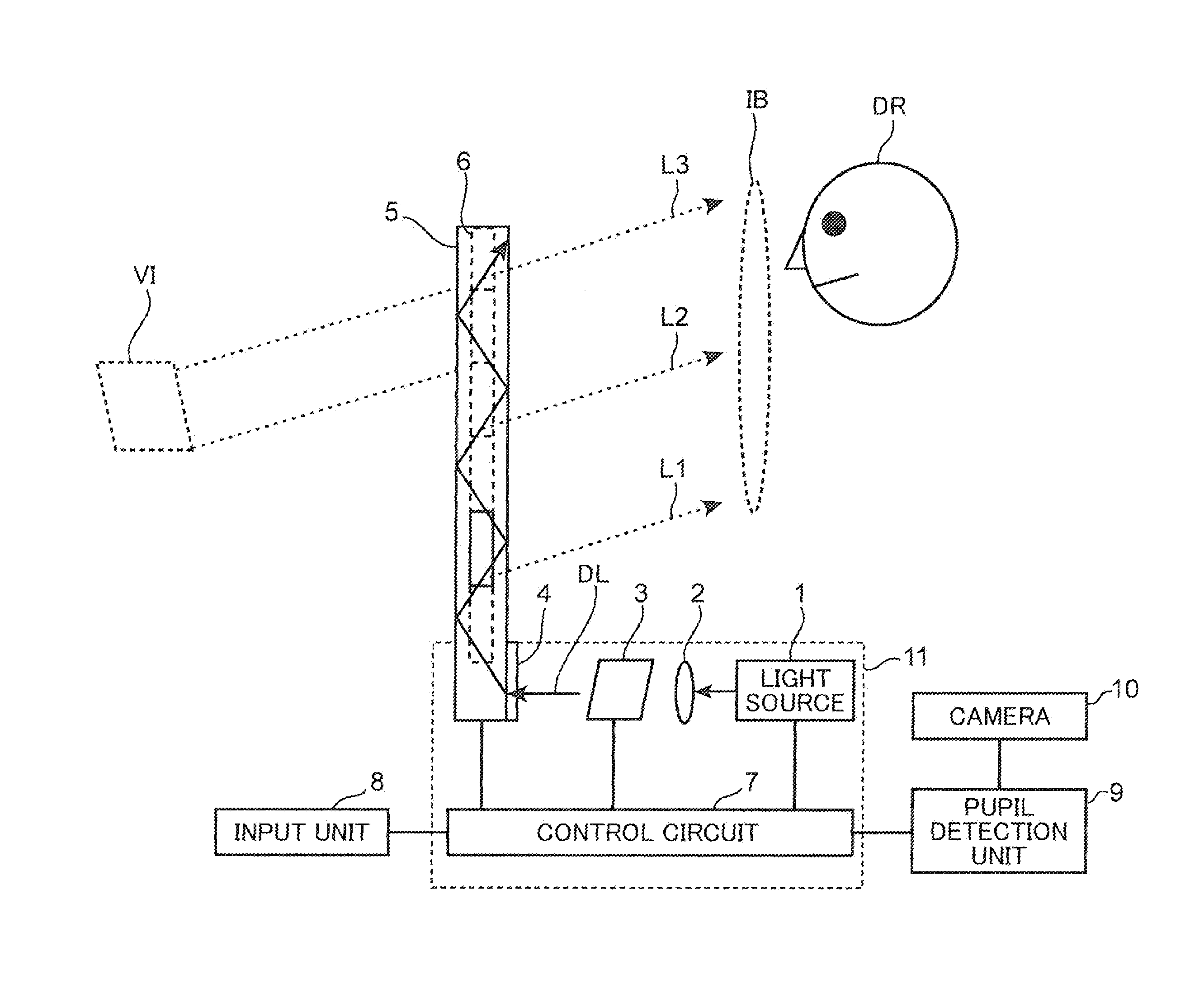
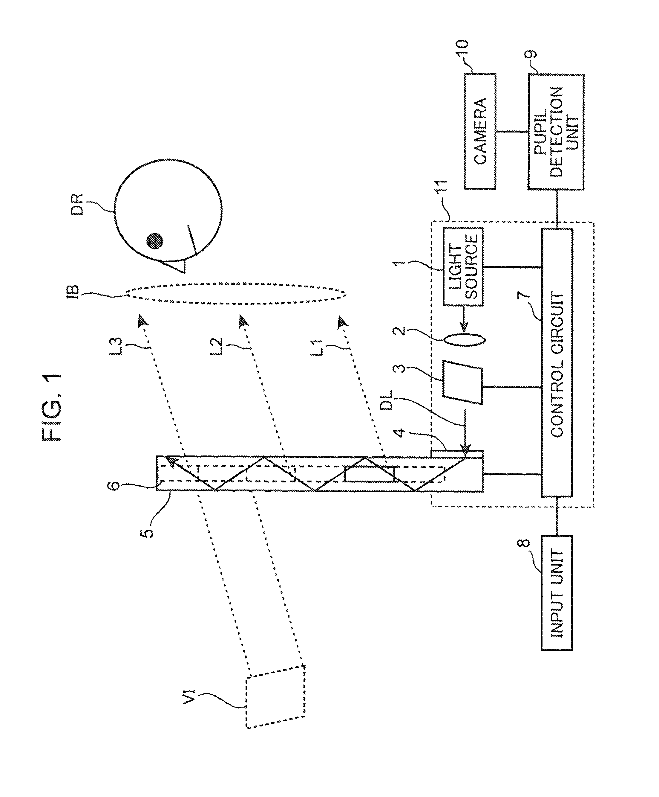
[0063]In the embodiment, there is described a method for suppressing stray light in an optical system of a HUD. FIG. 1 is a schematic diagram illustrating a configuration of a HUD (Head Up Display) according to the first embodiment of the invention. The HUD illustrated in FIG. 1 is a head up display loaded in e.g. an automobile and configured to display driving information to the driver DR. The HUD is provided with a light source 1, an incident optical system 2, a display element 3, an incident diffraction element 4, a light guiding plate 5, a dynamic output diffraction element 6, a control circuit 7, an input unit 8, a pupil detection unit 9, a camera 10, and a HUD housing 11. The control circuit 7 controls the operations of the light source 1, the display element 3, and the dynamic output diffraction element 6.

[0064]The HUD housing 11 is accommodated in the dashboard of a car. The light source 1, the incident optical system 2, the display element 3, the incident diffraction elemen...

second embodiment

[0095]In the embodiment, there is described a method for suppressing generation of stray light in a HUD optical system employing a light guiding plate. FIG. 6 is a diagram illustrating a configuration example of a light guiding plate and a polarizing plate to be used in the second embodiment of the invention. The configuration of the HUD in the embodiment is substantially the same as the configuration in FIG. 1 except that the incident diffraction element 4 and the light guiding plate 5 illustrated in FIG. 1 are changed to an incident diffraction element 4a and a light guiding plate 5a, and that a polarizing plate 21 is disposed on the side of the light guiding plate 5a provided with the incident diffraction element 4a, on which external light is incident. Accordingly, illustration and description of the constituent elements substantially the same as those in the first embodiment are omitted.

[0096]As illustrated in FIG. 6, in the embodiment, the polarizing plate 21 is disposed on th...

third embodiment

[0104]In the embodiment, there is described a measure against light scattering involved when a diffraction element is a dynamic diffraction element. As described above, the dynamic diffraction element is an element configured to record interference fringes in a material such as liquid crystal, and to validate or invalidate the diffraction function due to the interference fringes by voltage application. Generally, voltage application is performed by mounting a dynamic diffraction element on a transparent electrode in order to apply a voltage to the dynamic diffraction element. Use of the transparent electrode makes it possible to use the dynamic diffraction element as an output diffraction element within a light guiding plate, even in use of a see-through display through which the user visually recognizes the outside world, such as a HUD. Further, it is often the case that an ITO (Indium Tin Oxide) film having a high transmittance of visible light, and a high conductivity is used as ...


PUM

PropertyMeasurementUnit
blue wavelengthaaaaaaaaaa

Abstract

An image display device includes a light source which emits light, a display element which receives the light, from the light source for generating display light, a light guiding plate which causes the display light to propagate therein, an incident element which allows the display light from the display element to be incident into the light guiding plate, and a dynamic output diffraction element provided in the light guiding plate for outputting the display light to the outside of the light guiding plate. The dynamic output diffraction element includes dynamic diffraction segment elements configured such that a diffraction function of diffracting light is invalidated or validated by voltage application. The image display device further includes a control unit which controls the dynamic output diffraction element such that one dynamic diffraction segment element whose diffraction function is validated is selected each at a time from among the dynamic diffraction segment elements.

Description

TECHNICAL FIELD[0001]The present invention relates to an image display device which is compact and yet capable of displaying a large screen by combination of a light guiding plate and a diffraction element.BACKGROUND ART[0002]A driver driving a vehicle such as an automobile is required to grasp the state of the outside of the vehicle, read information of a display device of the vehicle, and drive the vehicle safely and speedily during driving. In view of this it is desirable to provide a configuration such that information of a display device of a vehicle is readable in a range necessary for grasping the state of the outside of the vehicle during driving. For instance, it is expected to implement an image display device for displaying characters or images by causing light to irradiate onto a part of a transparent plate such as a front glass of a vehicle.[0003]As examples of the transmissive image display device, there are known a head up display (hereinafter, called as “HUD”) for di...

Claims


Application Information

Patent Timeline
Patent Type & Authority Patents(United States)
IPC IPC(8): G02B26/08G06F3/01G02B27/00G02B5/18G02B27/01G02F1/29G02B26/00
CPCG02B5/18G02B27/0101G02B27/0093G02B27/0103G02F1/292G06F3/013G02B2027/0118G02B2027/014G02B17/08G02B25/02G02B27/4205
Inventor SUGIYAMA, KEIJIKASAZUMI, KENICHI
Owner PANASONIC INTELLECTUAL PROPERTY MANAGEMENT CO LTD
Why Eureka
Try Eureka