Eureka AIR delivers breakthrough ideas for toughest innovation challenges, trusted by R&D personnel around the world.

Use of Expandable Self-Removing Filler Material in Fracturing Operations

Active Publication Date: 2014-01-23
HALLIBURTON ENERGY SERVICES INC
View PDF4 Cites 14 Cited by
  • Summary
  • Abstract
  • Description
  • Claims
  • Application Information

AI Technical Summary

Benefits of technology

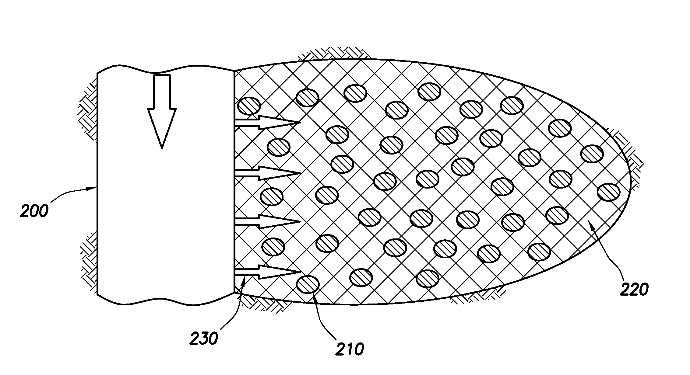
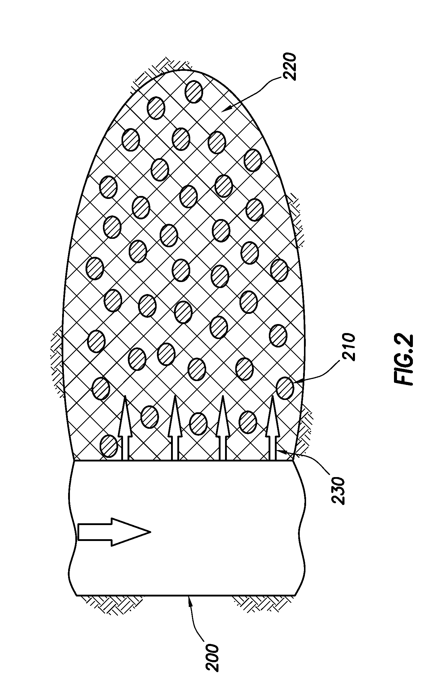
The present invention relates to fracturing operations and, more particularly, to compositions and methods related to proppant placement using an expandable material. The technical effect of the invention is to provide an improved method for placing proppant agents in a subterranean formation during fracturing operations that results in greater stability and increased conductivity of the fractured formation. This is achieved through the use of a propping fluid containing carrier fluid and propping agents, and a spacer fluid containing an expandable filler material that when expanded packs the propping agents into at least one proppant aggregate. This expands the expandable filler material into the fracture, providing stability and increased conductivity. Additionally, the expandable filler material may be allowed to degrade after placement, further enhancing the stability and conductivity of the fractured formation.

Problems solved by technology

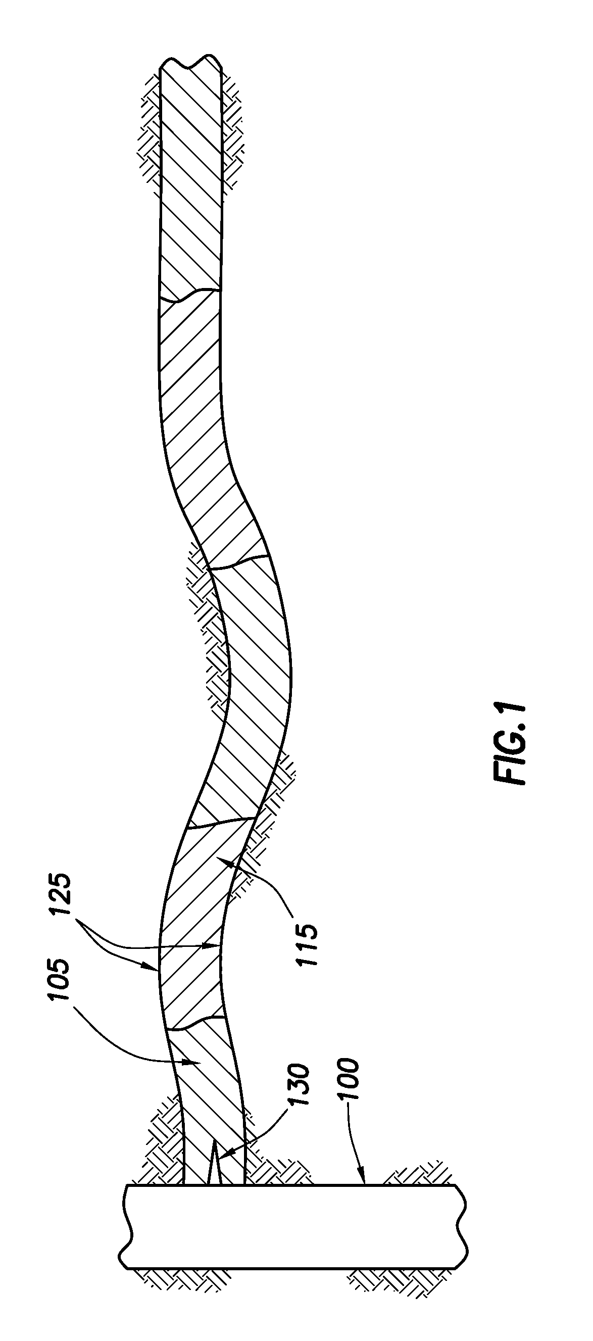
In some cases, the slurries contain proppants coated with adhesives, such that the proppants exhibit a sticky or tacky character and have a tendency to cluster or aggregate (i.e., form proppant pillars).
This results in a significant increase of the effective hydraulic conductivity of the overall fracture.
However, there are issues that limit the usefulness of heterogeneous proppant placement.
For example, proppant settling is especially problematic in heterogeneous proppant placement because reduced volumes of proppants are typically used.
Proppant settling may lead to closure of a portion of the fracture (typically the top portion), which can lower the conductivity of the propped fracture and result in proppant aggregation rather than the desired discrete pillars.
Moreover, one of the main technical challenges of heterogeneous proppant placement is the aggregation or formation of proppant pillars from individual proppants and / or proppant clusters.

Method used


Image

  • Use of Expandable Self-Removing Filler Material in Fracturing Operations
  • Use of Expandable Self-Removing Filler Material in Fracturing Operations
  • Use of Expandable Self-Removing Filler Material in Fracturing Operations

Examples


example 1

[0048]In this example, the expansion of boric oxide was experimentally observed over time.

[0049]Seven graduated cylinders, each containing approximately one milliliter (ml) of boric oxide particles, were observed. The cylinders were labeled: “Retained on 8,”“10 / 12,”“12 / 14,”“16 / 18,”“20 / 30,”“30 / 40,” and “40 / Pan;” indicating the size of the boric oxide particles in terms of U.S. mesh size. By way of example, particles retained on 8 U.S. mesh will be generally 2.38 mm or greater in size, whereas particles that went past 40 U.S. Mesh to the catch pan below will be smaller than about 0.4 mm. 10 ml of distilled water was added to each graduated cylinder using a syringe at time=0 minutes (min). Upon addition of distilled water, each boric acid sample demonstrated various expansion rates. The extent of expansion was measured (per about 0.25 ml) at approximately 1 min, 2 min, 10 min, and 25 min after addition of water, as represented in Table 1. Table 1 also demonstrates that smaller particle...


PUM


Abstract

A method using a propping fluid comprising a first carrier fluid and a plurality of propping agents and a spacer fluid comprising a second carrier fluid and an expandable filler material. The method introduces the propping fluid into a fracture in a subterranean formation and introduces the spacer fluid into the fracture. Then the expandable filler material is exposed to an expanding agent that causes the expandable filler material to expand and press against the adjacent propping agents.

Description

BACKGROUND[0001]The present invention relates to fracturing operations and, more particularly to, compositions and methods related to proppant placement using an expandable material.[0002]Fracturing (e.g., hydraulic fracturing) is a technique in which fractures are propagated in a subterranean formation by the introduction of a pressurized fluid. Often, fracturing operations are performed for the purpose of extracting certain materials such as petroleum, natural gas, coal seam gas, and the like. Hydraulic fracturing can be used to increase or restore the rate at which such materials can be produced from a subterranean formation.[0003]In a typical hydraulic fracturing operation, a proppant (also known in the art as a “propping agent”) is suspended in a portion of a treatment fluid, which may then be transported and deposited in fractures within the subterranean formation. The proppant serves to prevent the fractures from fully closing so that conductive channels are formed through wh...

Claims


Application Information

Patent Timeline
IPC IPC(8): E21B43/267E21B43/26
CPCC09K8/62C09K8/80E21B43/267
Inventor SMITH, JONATHAN PAULWORLEY, JONATHANALLISON, DAVE B.KLEINWOLTERINK, KEMBE DANE
Owner HALLIBURTON ENERGY SERVICES INC
Why Eureka
Eureka Blog
Learn More