Image capture apparatus and control method thereof, and lens unit
a technology of image capture and control method, applied in the field of image capture apparatus and control method, can solve problems such as improper correction, image quality deterioration, and difficulty in implementing a lens unit that completely eliminates such characteristics
- Summary
- Abstract
- Description
- Claims
- Application Information
AI Technical Summary
Benefits of technology
Problems solved by technology
Method used
Image
Examples
first embodiment
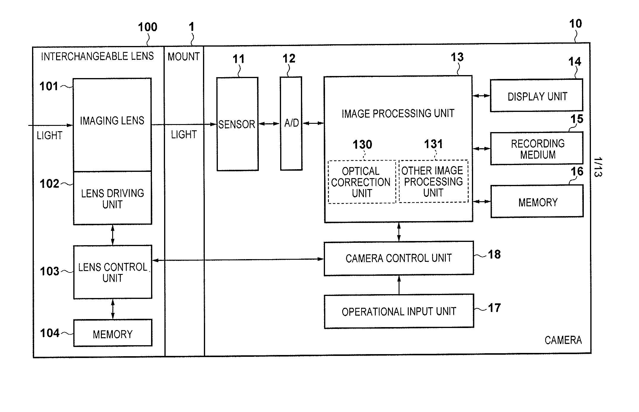
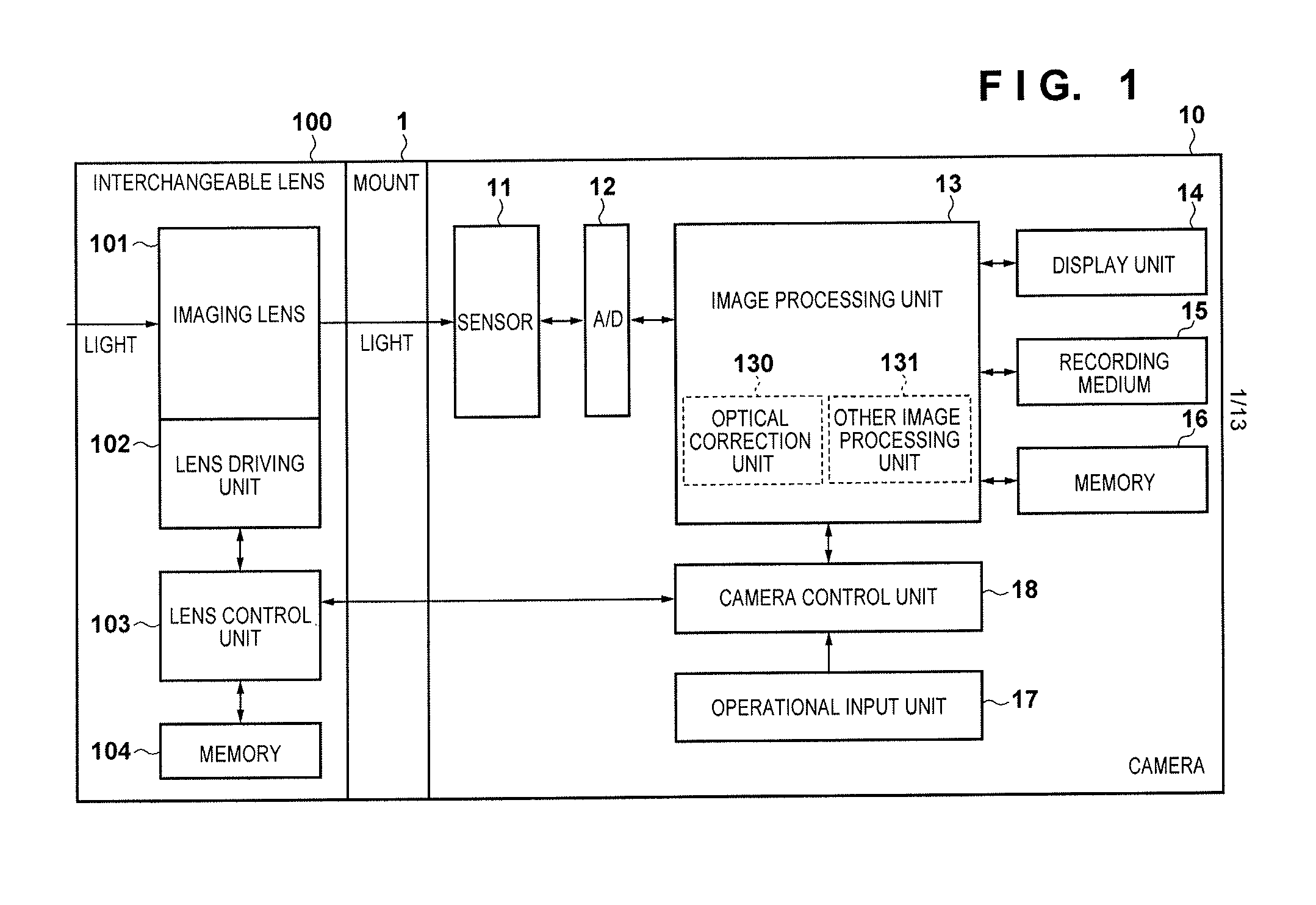
[0039]FIG. 1 is a block diagram illustrating an example of the functional configuration of an interchangeable lens-type digital camera system serving as an example of an image capture apparatus according to a first embodiment of the present invention. The camera system is configured of a camera 10 and an interchangeable lens 100, which is a lens unit that can be attached to / detached from the camera 10. A mount 1 is a mechanism for attaching the interchangeable lens 100 to the camera 10 in a detachable state, and includes electrical connection points for enabling the camera 10 to supply power to the interchangeable lens 100, enabling the camera 10 and the interchangeable lens 100 communicate with each other, and so on. The mount 1 is divided into a section provided in the camera 10 and a section provided in the interchangeable lens 100, but is illustrated in FIG. 1 as a single unit for the sake of simplicity.
[0040]An image sensor (imaging element) 11 is a photoelectric conversion dev...
second embodiment
[0114]Next, a second embodiment of the present invention will be described.
[0115]The basic configuration of the image capture apparatus and the terminals provided in the mount 1 in the present embodiment are the same as those described in the first embodiment, but the present embodiment assumes that the second interchangeable lens is configured to transmit the optical correction data from the lens to the camera. Accordingly, the optical correction data is stored in the memory 104 provided in the second interchangeable lens. The optical correction data held here has the structure illustrated in FIG. 9B.
[0116]FIG. 12 is a flowchart illustrating a lens type determination process, an optical correction data receiving process, and a process for receiving the optical parameters used during shooting that are necessary to identify an optical correction value, carried out by the camera microcomputer 20 in the camera system according to the present embodiment. These processes are carried out ...
PUM
 Abstract
Description
Claims
Application Information
 - R&D
- Intellectual Property
- Life Sciences
- Materials
- Tech Scout
- Unparalleled Data Quality
- Higher Quality Content
- 60% Fewer Hallucinations
Browse by: Latest US Patents, China's latest patents, Technical Efficacy Thesaurus, Application Domain, Technology Topic, Popular Technical Reports.
© 2025 PatSnap. All rights reserved.Legal|Privacy policy|Modern Slavery Act Transparency Statement|Sitemap|About US| Contact US: help@patsnap.com


