Panoramic optical systems

a panoramic optical system and optical system technology, applied in optics, optical elements, instruments, etc., can solve the problems of reducing the resolution of the portion of the field near the horizontal plane, and not allowing much light to reach the image through the pinhole, so as to minimize astigmatism and minimize astigmatism

Inactive Publication Date: 2014-01-23
360AI SOLUTIONS LLC
View PDF1 Cites 36 Cited by
  • Summary
  • Abstract
  • Description
  • Claims
  • Application Information

AI Technical Summary

Benefits of technology

[0016]The present invention provides periscopic lens systems with a single mirror designed to minimize astigmatism. Simple, highly manufacturable lens systems are provided for capturing and / or projecting a 360-degree panoramic scene that requires only a single mirror. Despite their simplicity, the lens systems are designed to be used at fast speeds, e.g., faster than F / 10. To achieve this combination of simplicity and speed, an ellipsoidal mirror is used to minimize astigmatism in combination with a dioptric lens group that counterbalances the aberrations introduced by the ellipsoidal mirror.

Problems solved by technology

However, a major problem with multiple cameras is stitching the images together to form a panorama.
Carefully scanning a single camera can alleviate this difficulty, but accurately moving a camera introduces an additional set of difficulties.
However, fisheye lenses often have significant image compression (distortion) at the edge of the field of view, resulting in decreased resolution in the portion of the field near the horizontal plane.
A significant problem with this type of system is that a pinhole does not allow much light to get to the image.
Although there are certain advantages to such designs, an overriding difficulty is the difficulty and complexity of fabricating the elements.
Multiple-catadioptric systems may be capable of high performance, but suffer the difficulty of aligning the mirrors and keeping them in alignment.
Although blur sizes of less than 10 microns at F / 1.5 are shown, the optical arrangement is extremely complex.
Such aberrations adversely affect the quality of the images.
The aberrations that are most significant in panoramic lenses are astigmatism and distortion because the field angle is so large.
The former method is impractical to manufacture for commercial purposes due to its complexity, and the latter can be impractical for photography because it requires the scene to be brightly illuminated.

Method used


Image

  • Panoramic optical systems
  • Panoramic optical systems
  • Panoramic optical systems

Examples


Embodiment Construction

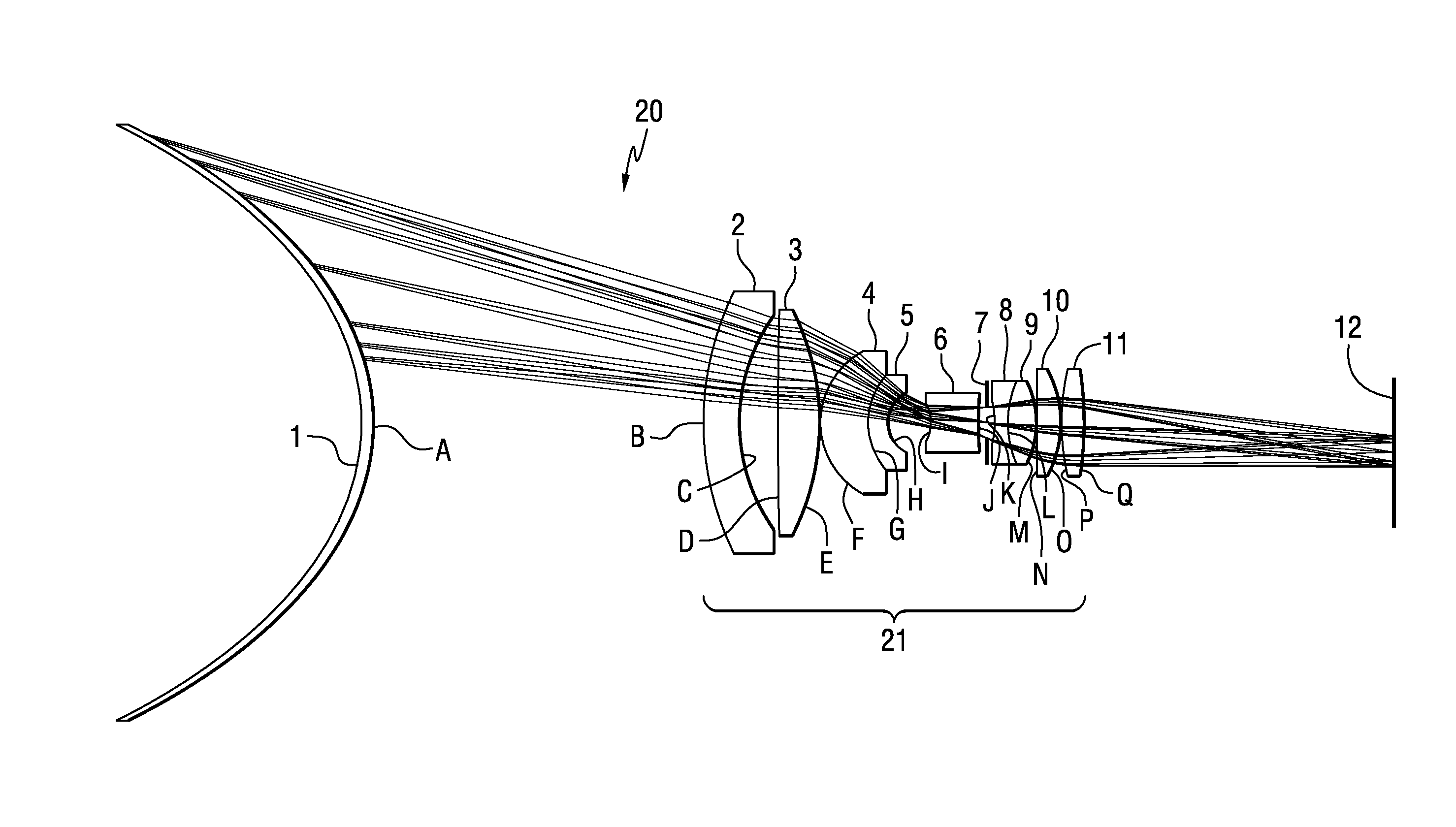
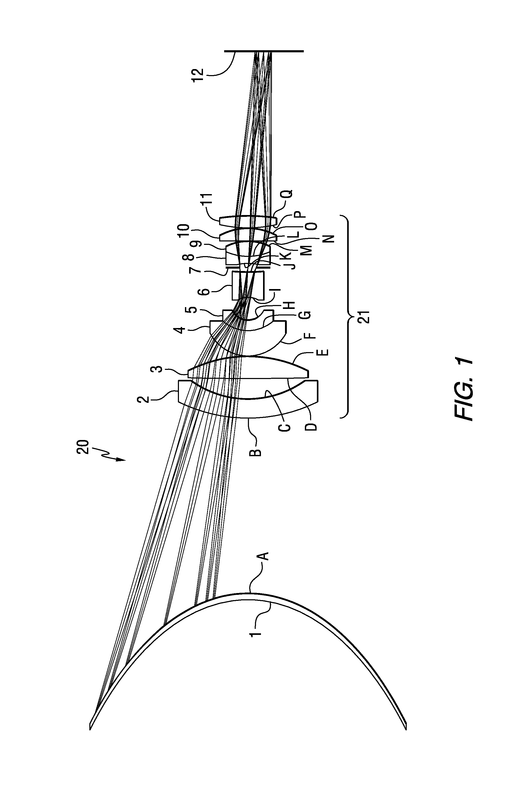
[0024]The panoramic optical system of the present invention comprises an ellipsoidal mirror and multiple dioptric lens elements. The ellipsoidal mirror is designed to minimize astigmatism and the dioptric lens elements counterbalance aberrations introduced by the mirror.

[0025]Referring to FIG. 1, a panoramic optical system 20 in accordance with an embodiment of the present invention includes a single ellipsoidal mirror 1 and a dioptric group or lens system 21. The mirror 1 is elliptical in form to minimize astigmatism, compared to spherical, parabolic or hyperbolic mirrors that introduce significantly more astigmatism.

[0026]The dioptric group 21 includes a multiplicity of dioptric elements 2-6 and 8-11 and an aperture stop 7. Light enters the dioptric group 21 after reflecting from the mirror 1. As it passes through the dioptric group 21 it passes through the aperture stop 7, which limits the F / number of the beam.

[0027]The aperture stop 7 may be made of a single part, such as a shee...


PUM


Abstract

Panoramic optical systems are disclosed comprising an ellipsoidal mirror and a lens system that reduces astigmatism. The lens systems are capable of operating at fast speeds. Simple and highly manufacturable lens systems are provided for capturing and / or projecting high quality 360-degree panoramic scenes.

Description

CROSS-REFERENCE TO RELATED APPLICATION[0001]This application claims the benefit of U.S. Provisional Patent Application Ser. No. 61 / 584,566 filed Jan. 9, 2012, which is incorporated herein by reference.FIELD OF THE INVENTION[0002]The present invention relates to panoramic optical systems, and in particular, it relates to catadioptric panoramic optical systems comprising a mirror and multiple transmissive elements.BACKGROUND INFORMATION[0003]Many rotationally symmetric lenses have been described over the years, and most of them are capable of imaging an azimuthal field of 360° about the axis of rotation, also called the optical axis. What distinguishes panoramic lenses is that their field of view is not measured from 0° at the optical axis to their maximum field, rather their field of view is measured with respect to a plane perpendicular to the optical axis. This plane is often referred to as the horizontal plane. For example, for a panoramic lens, the field of view may be referred t...

Claims


Application Information

Patent Timeline
Patent Type & Authority Applications(United States)
IPC IPC(8): G02B13/06
CPCG02B13/06G02B17/08G02B17/0852G02B17/086
Inventor ECKHARDT, STEPHEN K.
Owner 360AI SOLUTIONS LLC
Why Eureka
Try Eureka