Projection zoom lens system and projection type display apparatus

a projection zoom and lens system technology, applied in the field of projection zoom lens system and projection type display apparatus, can solve the problems of large spherical aberration accompanied by zooming, large marginal ray fluctuation, and increase in astigmatism, so as to reduce astigmatism, reduce marginal ray fluctuation, and effectively correct marginal rays

Inactive Publication Date: 2010-05-11
FUJI PHOTO OPTICAL CO LTD
View PDF12 Cites 13 Cited by
  • Summary
  • Abstract
  • Description
  • Claims
  • Application Information

AI Technical Summary

Benefits of technology

[0010]The invention has been made in view of the above circumstances, and provides a high-resolution projection zoom lens system capable of reducing the astigmatism while reducing fluctuation of the spherical aberration accompanied by zooming. The invention also provides a projection type display apparatus having the projection zoom lens system.
[0019]The above-mentioned configuration of the projection zoom lens system according to the one aspect of the invention has the following advantages.
[0021]In the projection zoom lens system according to the one aspect of the invention, the negative lens LN, which satisfies the conditional expression (1A) and includes the concave surface having the negative power, is disposed in the third lens group disposed close to the magnification side. With such a configuration, an axial marginal ray associated with the spherical aberration can be corrected at a position where a ray height is large. Thus, it is possible to effectively correct marginal rays, and it is also possible to reduce fluctuation of the spherical aberration accompanied by zooming. In addition, the concave surface of the negative lens LN is disposed to direct to the reduction side. Thereby, it is possible to reduce the astigmatism.

Problems solved by technology

However, there arise such problems that fluctuation of the spherical aberration accompanied by zooming is large and that a marginal ray tends to be largely under especially at the telephoto end.
However, in the projection zoom lens system described in JP 2005-84455 A, fluctuation of the spherical aberration accompanied by zooming decreases, but a problem arises that the astigmatism increases.

Method used


Image

  • Projection zoom lens system and projection type display apparatus
  • Projection zoom lens system and projection type display apparatus
  • Projection zoom lens system and projection type display apparatus

Examples


example 1

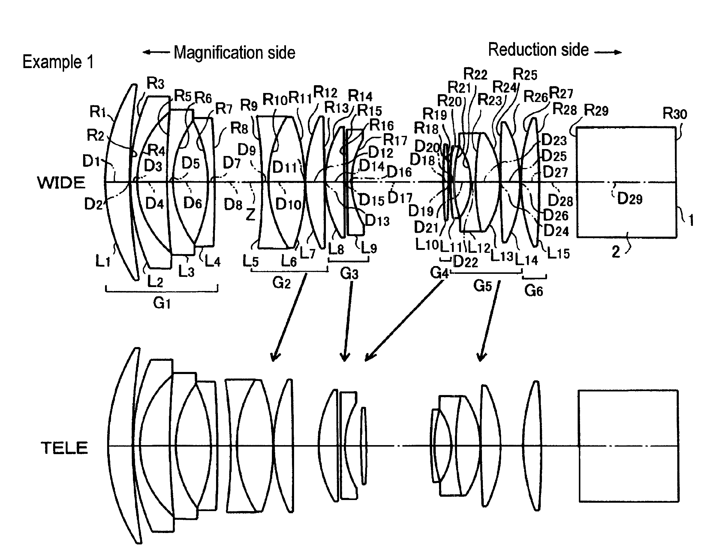
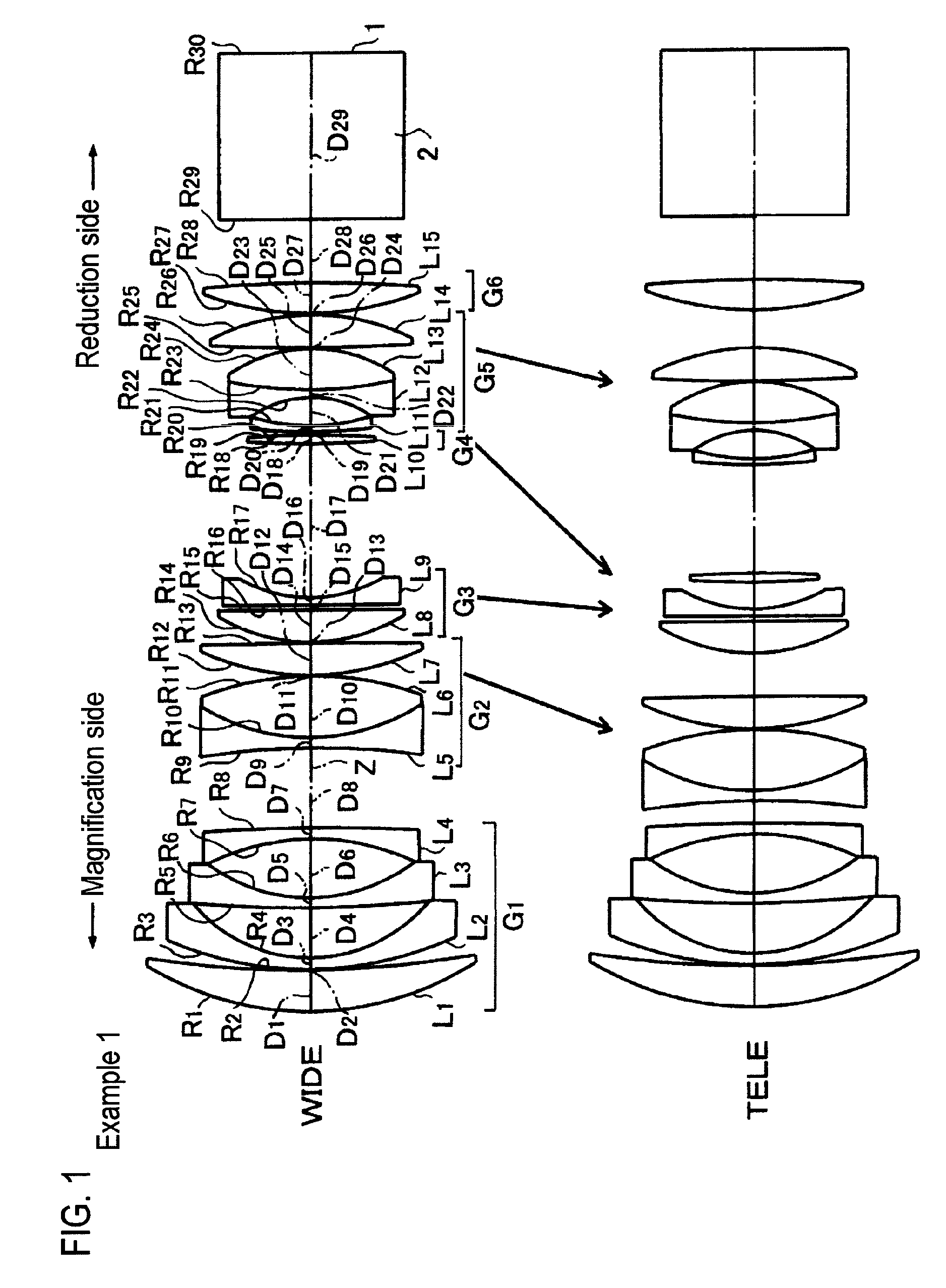
[0056]FIG. 1 shows the schematic configuration of the projection zoom lens system according to Example 1. The projection zoom lens system includes, in order from the magnification side, a first lens group G1 having a negative refractive power, a second lens group G2 having a positive refractive power, a third lens group G3 having a negative refractive power, a fourth lens group G4 having a positive refractive power, a fifth lens group G5 having a positive refractive power, and a sixth lens group G6 having a positive refractive power. The lens system is nearly telecentric on the reduction side.

[0057]Here, the first lens group G1 includes, in order from the magnification side, a first lens L1 formed of a positive meniscus lens having a convex surface directed to the magnification side, a second lens L2 formed of a negative meniscus lens having a convex surface directed to the magnification side, a third lens L3 formed of a negative meniscus lens having a convex surface directed to the...

example 2

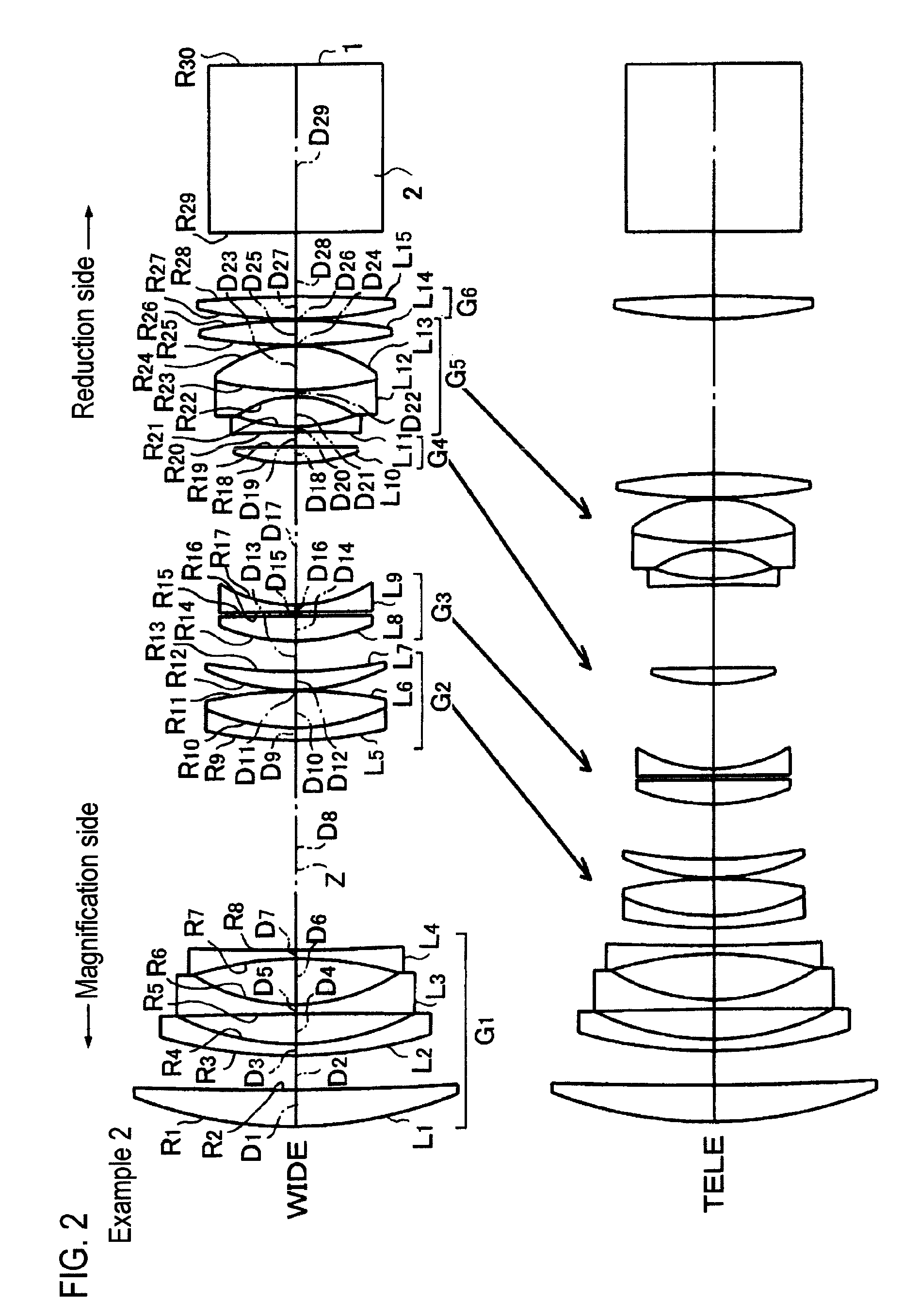
[0067]FIG. 2 shows the schematic configuration of a projection zoom lens system according to Example 2. The projection zoom lens system includes, in order from the magnification side, a first lens group G1 having a negative refractive power, a second lens group G2 having a positive refractive power, a third lens group G3 having a negative refractive power, a fourth lens group G4 having a positive refractive power, a fifth lens group G5 having a negative refractive power, and a sixth lens group G6 having a positive refractive power. The lens system is nearly telecentric on the reduction side thereof.

[0068]Here, the first lens group G1 includes, in order from the magnification side, a first lens L1 formed of a positive meniscus lens having a convex surface directed to the magnification side, a second lens L2 formed of a negative meniscus lens having a convex surface directed to the magnification side, a third lens L3 formed of a biconcave lens, and a fourth lens L4 formed of a biconca...

example 3

[0077]FIG. 3 shows the schematic configuration of a projection zoom lens system according to Example 3. The projection zoom lens system includes, in order from the magnification side, a first lens group G1 having a negative refractive power, a second lens group G2 having a positive refractive power, a third lens group G3 having a positive refractive power, a mask 3, a fourth lens group G4 having a positive refractive power, a fifth lens group G5 having a negative refractive power, and a sixth lens group G6 having a positive refractive power. The lens system is nearly telecentric on the reduction side.

[0078]Here, the first lens group G1 includes, in order from the magnification side, a first lens L1 formed of a positive meniscus lens having a convex surface directed to the magnification side, a second lens L2 formed of a negative meniscus lens having a convex surface directed to the magnification side, a third lens L3 formed of a negative meniscus lens having a concave surface direct...


PUM


Abstract

The projection zoom lens system includes a negative first lens group, a positive second lens group, a third lens group, a positive fourth lens group, a fifth lens group, and a positive sixth lens group. The lens system is nearly telecentric on a reduction side. During zooming, the second to fifth lens groups are moved while the first and six lens groups remain stationary. The third lens group includes a positive lens LP having a convex surface directed to a magnification side, and a negative lens LN having a concave surface which is directed to the reduction side and has a curvature stronger than a magnification-side surface of the negative lens LN. The conditional expression of 5.0≦|fG3 / RLN-2| is satisfied. Here, fG3 denotes a focal length of the third lens group, and RLN-2 denotes a radius of curvature of the reduction-side surface of the negative lens LN.

Description

CROSS-REFERENCE TO RELATED APPLICATIONS[0001]This application is based upon and claims the benefit of priority from the Japanese Patent Application No. 2008-50335 filed on Feb. 29, 2008; the entire contents of which are incorporated herein by reference.BACKGROUND OF THE INVENTION[0002]1. Technical Field[0003]The invention relates to a projection zoom lens system having a six-group configuration and a projection type display apparatus having the projection zoom lens system. In particular, the invention relates to a projection zoom lens system configured to project and magnify onto a screen, rays which contain image information and are generated from a light valve such as a liquid crystal display device or a DMD (Digital Micromirror Device) display device, and a projection type display apparatus having the projection zoom lens system.[0004]2. Description of the Related Art[0005]Recently, beam projectors (projection display devices) using light valves such as transmissive or reflective...

Claims


Application Information

Patent Timeline
Patent Type & Authority Patents(United States)
IPC IPC(8): G02B15/14
CPCG02B15/177G02B15/1465
Inventor YAMAMOTO, CHIKARAAMANO, MASARU
Owner FUJI PHOTO OPTICAL CO LTD
Why Eureka
Try Eureka