
Optical disc apparatus, optical pickup apparatus, and method for reducing astigmatism

a technology of optical discs and pickups, applied in the field of optical discs and optical pickups, can solve the problems of difficult to reduce difficult to reduce the astigmatism, and achieve the effects of accurately recording and reproducing, and reducing the size of the apparatus

Inactive Publication Date: 2007-07-19
SONY CORP
View PDF9 Cites 9 Cited by
  • Summary
  • Abstract
  • Description
  • Claims
  • Application Information

AI Technical Summary

Benefits of technology

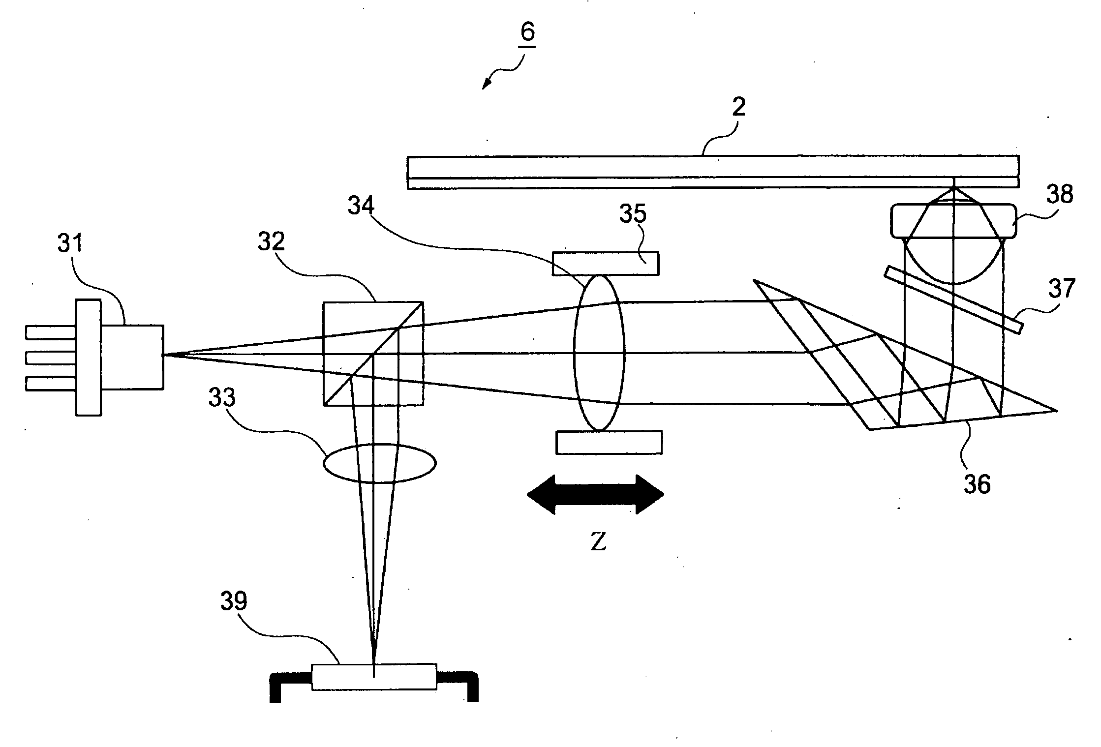
The present invention provides an optical pickup apparatus and an optical disc apparatus that can dynamically correct spherical aberration and reduce astigmatism without making it difficult to reduce the size of the apparatuses and accurately recording and reproducing information without redundancy. The apparatuses include an upward directing prism that changes the direction of the optical axis of the laser beam, a collimator lens, an objective lens, and a unit for changing the angle of divergence or convergence of the laser beam incident on the objective lens. The beam-shaping magnification of the upward directing prism is set within the range of 0.97<β<1.03. The technical effects of the invention include reducing astigmatism, accurately recording and reproducing information without redundancy, and reducing the size of the apparatuses.

Problems solved by technology

However, the structure described in U.S. Pat. No. 6,151,154 includes a relatively large number of components including the liquid crystal device and it is difficult to reduce the size of the apparatus.
Therefore, it is difficult to reduce the astigmatism by applying the above-mentioned technique described in U.S. Pat. No. 6,151,154.

Method used


Image

  • Optical disc apparatus, optical pickup apparatus, and method for reducing astigmatism
  • Optical disc apparatus, optical pickup apparatus, and method for reducing astigmatism
  • Optical disc apparatus, optical pickup apparatus, and method for reducing astigmatism

Examples


first embodiment

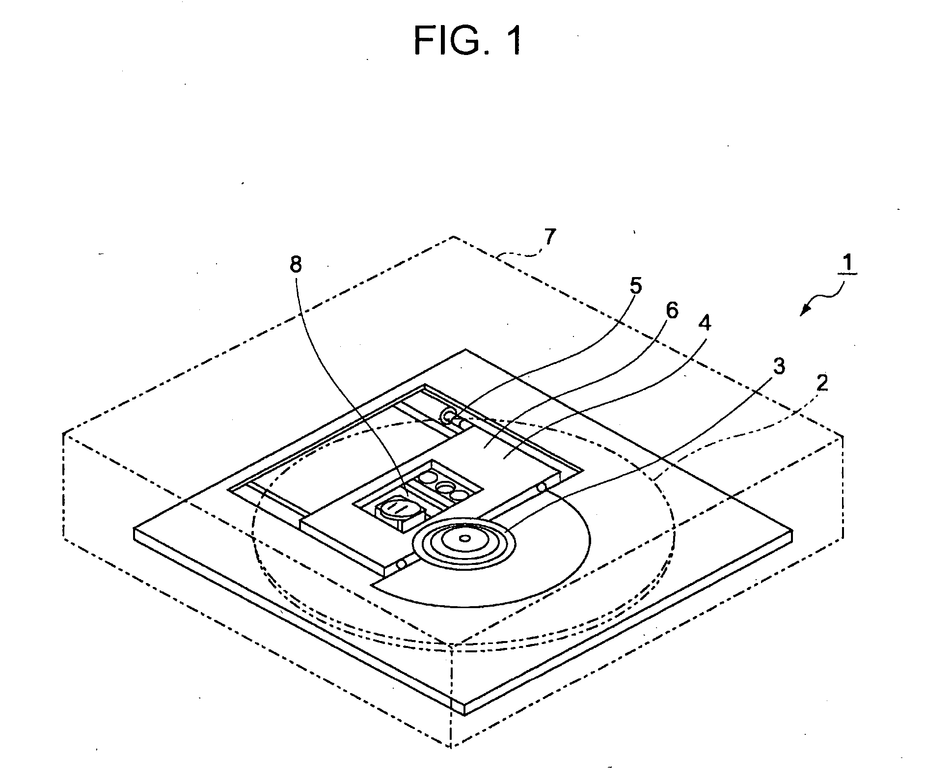
[0038]FIG. 1 is a perspective view of an optical disc apparatus 1 according to a first embodiment of the present invention.

[0039] The optical disc apparatus 1 shown in FIG. 1 records and reproduces information on and from an optical disc 2 (DVD±R / RW, CD-R / RW, BD, etc.) mounted therein. When the optical disc 2 is a double-layer Blu-ray disc (trademark), the error range of the thickness of each protective layer is determined to be 12.5 μm or less by a standard.

[0040] The optical disc apparatus 1 includes a disc table 3 for receiving the optical disc 2, such as a BD, a moveable base 4, a guide shaft 5 for guiding the moveable base 4, an optical pickup 6 for recording and reproducing information on and from the optical disc 2, and a housing 7 for accommodating the above-described components.

[0041] The disc table 3 has a chucking mechanism for holding the optical disc 2, and accordingly the disc table 3 can, for example, rotate while the optical disc 2 is attached to the disc table 3....


PUM

PropertyMeasurementUnit
βaaaaaaaaaa
thicknessaaaaaaaaaa
refractive indexaaaaaaaaaa

Abstract

An optical disc apparatus includes a light source that emits a laser beam; a collimator lens arranged on an optical axis of the emitted laser beam; a upward directing prism that changes the direction of the optical axis of the laser beam output from the collimator lens by approximately 90°, the upward directing prism having a beam-shaping magnification β in the range of 0.97<β<1.03; an objective lens that condenses the laser beam on an optical disc having a protective layer with a thickness error range of 12.5 μm after the direction of the optical axis is changed by the upward directing prism, the objective lens having a numerical aperture NA of 0.85; and a unit for changing an angle of divergence or convergence of the laser beam incident on the objective lens.

Description

CROSS REFERENCES TO RELATED APPLICATIONS [0001] The present invention contains subject matter related to Japanese Patent Applications JP 2006-005646 filed in the Japanese Patent Office on Jan. 13, 2006 and JP 2006-132934 filed in the Japanese Patent Office on May 11, 2006, the entire contents of which are incorporated herein by reference. BACKGROUND OF THE INVENTION [0002] 1. Field of the Invention [0003] The present invention relates to an optical disc apparatus and an optical pickup apparatus for optically recording and reproducing information on and from an optical disc, and also relates to an astigmatism reducing method that may be used in the optical disc apparatus and the optical pickup apparatus. [0004] 2. Description of the Related Art [0005] Recently, the size of personal computers and the like has been reduced, and accordingly there has been a demand to reduce the size of optical disc apparatuses contained therein. To satisfy such a demand, a technique for reducing the thi...

Claims


Application Information

Patent Timeline
Patent Type & Authority Applications(United States)
IPC IPC(8): G11B7/00
CPCG11B7/0948G11B7/1359G11B2007/0013G11B7/13927G11B7/1398G11B7/1376
Inventor YAMAMOTO, KENJI
Owner SONY CORP
Learn More