Connection mechanism for pivotally connecting two link rods

Inactive Publication Date: 2014-01-23
LEE YU CHIEH
View PDF12 Cites 2 Cited by
  • Summary
  • Abstract
  • Description
  • Claims
  • Application Information

AI Technical Summary

Benefits of technology

[0015]With the above arrangements, the connection mechanism of the present invention provides the advantage o

Problems solved by technology

The conventional connection mechanism with the above-described structure is disadvantageous for use because the washers tend to rotate along with the pivot shaft

Method used


Image

  • Connection mechanism for pivotally connecting two link rods
  • Connection mechanism for pivotally connecting two link rods
  • Connection mechanism for pivotally connecting two link rods

Examples


Embodiment Construction

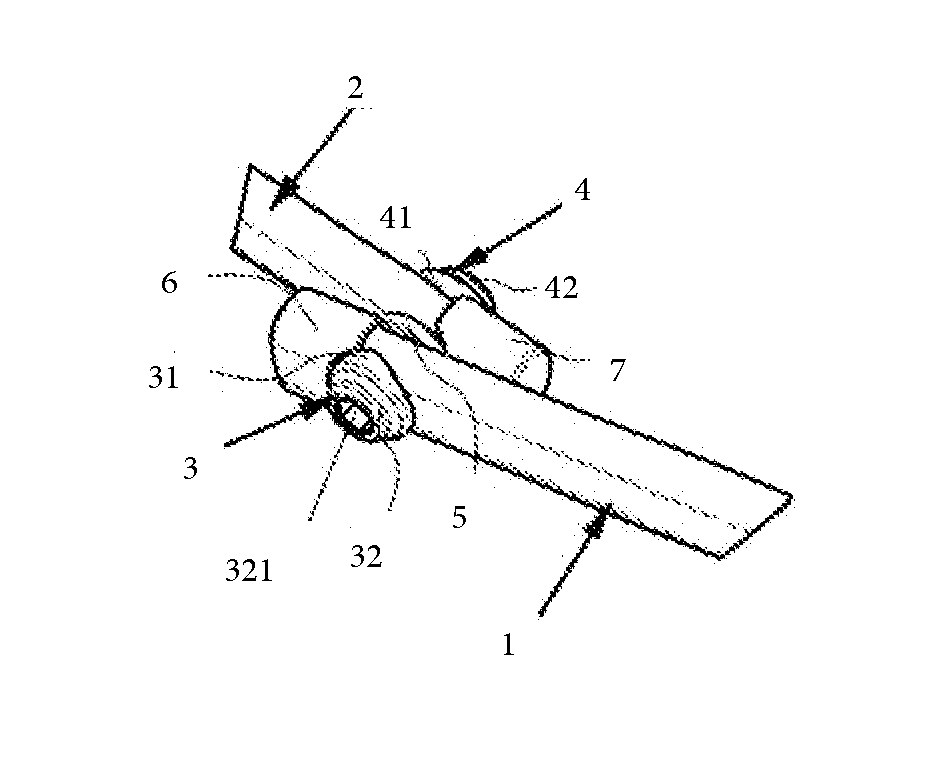
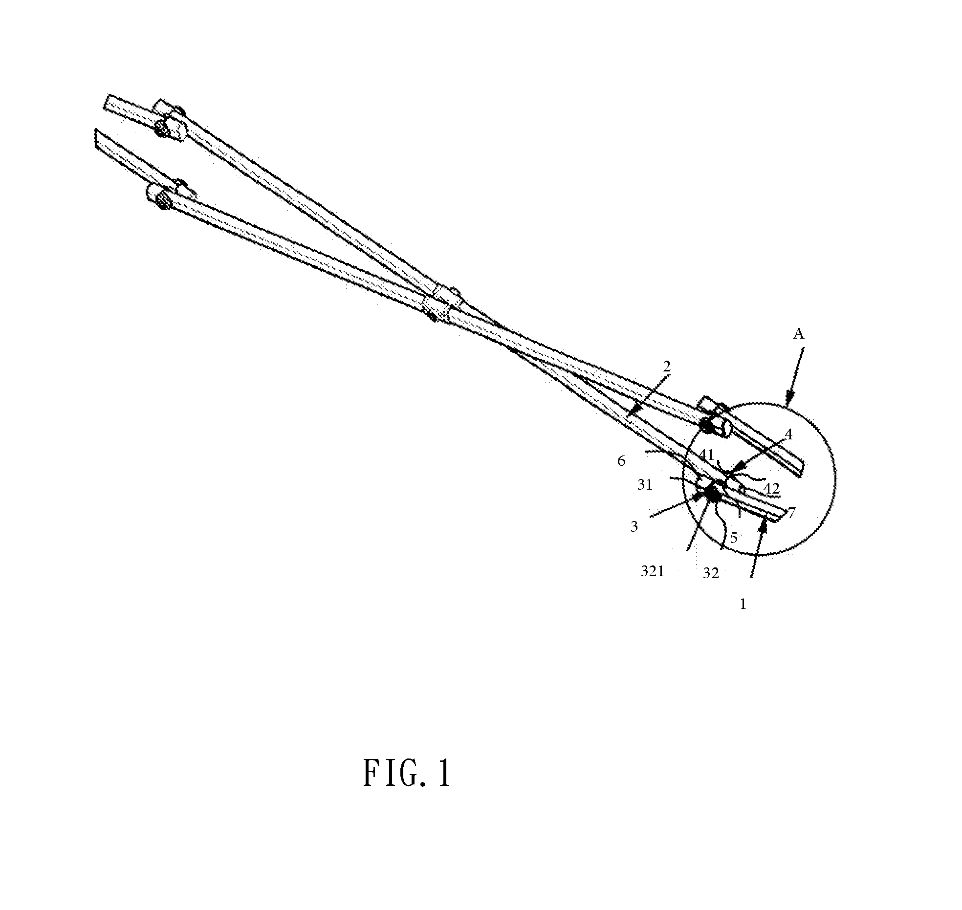
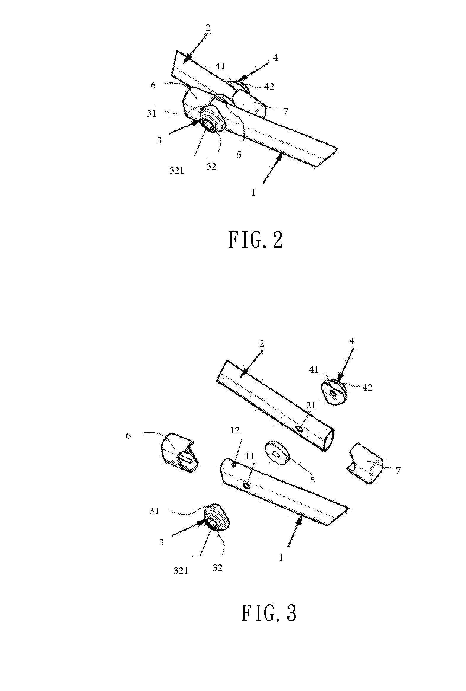
[0021]Please refer to FIG. 1. A connection mechanism according to the present invention is used to pivotally connect two link rods of two scissor linkages. More specifically, the connection mechanism of the present invention is used to pivotally connect a first link rod 1 of a first scissor linkage and a second link rod 2 of a second scissor linkage to each other. As can be seen from FIGS. 1, 2 and 3, the connection mechanism includes a first connection seat 3, a second connection seat 4, a washer 5, a first reinforcing cap 6, a second reinforcing cap 7, a bolt, and a nut.

[0022]As can be best seen from FIG. 3, the first link rod 1 has a rectangular-like cross section and is provided close to an end with a pivot hole 11. The first link rod 1 is also provided closer to the end with a fixed first locating dot 12. The second link rod 2 has a rectangular-like cross section and is provided close to an end with a pivot hole 21. The second link rod 2 is also provided closer to the end with ...


PUM


Abstract

A connection mechanism for pivotally connecting two link rods, namely, a first link rod of a scissor linkage and a second link rod of another scissor linkage, includes a first connection seat having a fitting surface for non-rotatably bearing on an outer side surface of the first link rod facing away from the second link rod; a second connection seat having a fitting surface for non-rotatably bearing on an outer side surface of the second link rod facing away from the first link rod; and a pivot shaft being sequentially extended through and locked to the second connection seat, the second link rod, the first link rod and the first connection seat. The connection seats are non-rotatably attached to the link rods and do not rotate along with the pivot shaft when the pivot shaft is turned to connect or separate the link rods to or from each other.

Description

FIELD OF THE INVENTION[0001]The present invention relates to a connection mechanism for pivotally connecting two link rods to each other.BACKGROUND OF THE INVENTION[0002]A conventional connection mechanism for pivotally connecting two link rods generally includes a pivot shaft and two washers. The two washers are separately arranged on two outer side surfaces of the two link rods facing away from each other. The pivot shaft is extended through the two link rods and the two washers and locked thereto. The conventional connection mechanism with the above-described structure is disadvantageous for use because the washers tend to rotate along with the pivot shaft and cause troubles when the pivot shaft is turned to extend through or loosen from the two link rods for connecting or disconnecting them to or from each other.SUMMARY OF THE INVENTION[0003]It is therefore a primary object of the present invention to provide an improved connection mechanism for pivotally connecting two link rod...

Claims


Application Information

Patent Timeline
IPC IPC(8): F16C11/04
CPCF16C11/04E04H15/50F16C2350/00Y10T403/32951
Inventor LEE, YU CHIEH
Owner LEE YU CHIEH
Why Eureka
Try Eureka