Nonaqueous secondary battery and filling method for same

Inactive Publication Date: 2014-01-23
SHARP KK
View PDF9 Cites 7 Cited by
  • Summary
  • Abstract
  • Description
  • Claims
  • Application Information

AI Technical Summary

Benefits of technology

The present invention can prevent the electrolyte from leaking out of the battery can, shorten the filling time, and prevent a reduction in battery capacity.

Problems solved by technology

However, the technique disclosed in Japanese Unexamined Patent Application Publication No. 10-241741 has the following problem.
Therefore, the gas is not smoothly replaced with the electrolyte in an inner space defined by the exterior can and the sealing member, and a filling time is prolonged.
Accordingly, there is a risk that the electrolyte may leak out from the container.
As another problem, because the electrolyte attaches to the hole in the bottom portion of the container, sealing-off of the hole in the bottom portion of the container is more apt to become insufficient.
This also results in a risk that the electrolyte may leak out from the container.
This raises a difficulty in uniformly infiltrating the electrolyte into the electrode assembly.
Hence, there is a fear that a time required to impregnate the entirety of the assembly uniformly with the electrolyte, i.e., a filling time, may be prolonged, or that the battery capacity may be extremely reduced with repeated use of the battery.

Method used


Image

  • Nonaqueous secondary battery and filling method for same
  • Nonaqueous secondary battery and filling method for same
  • Nonaqueous secondary battery and filling method for same

Examples


example 1

[0071]The nonaqueous secondary battery 1 was fabricated in accordance with the above-described method for fabricating the nonaqueous secondary battery.

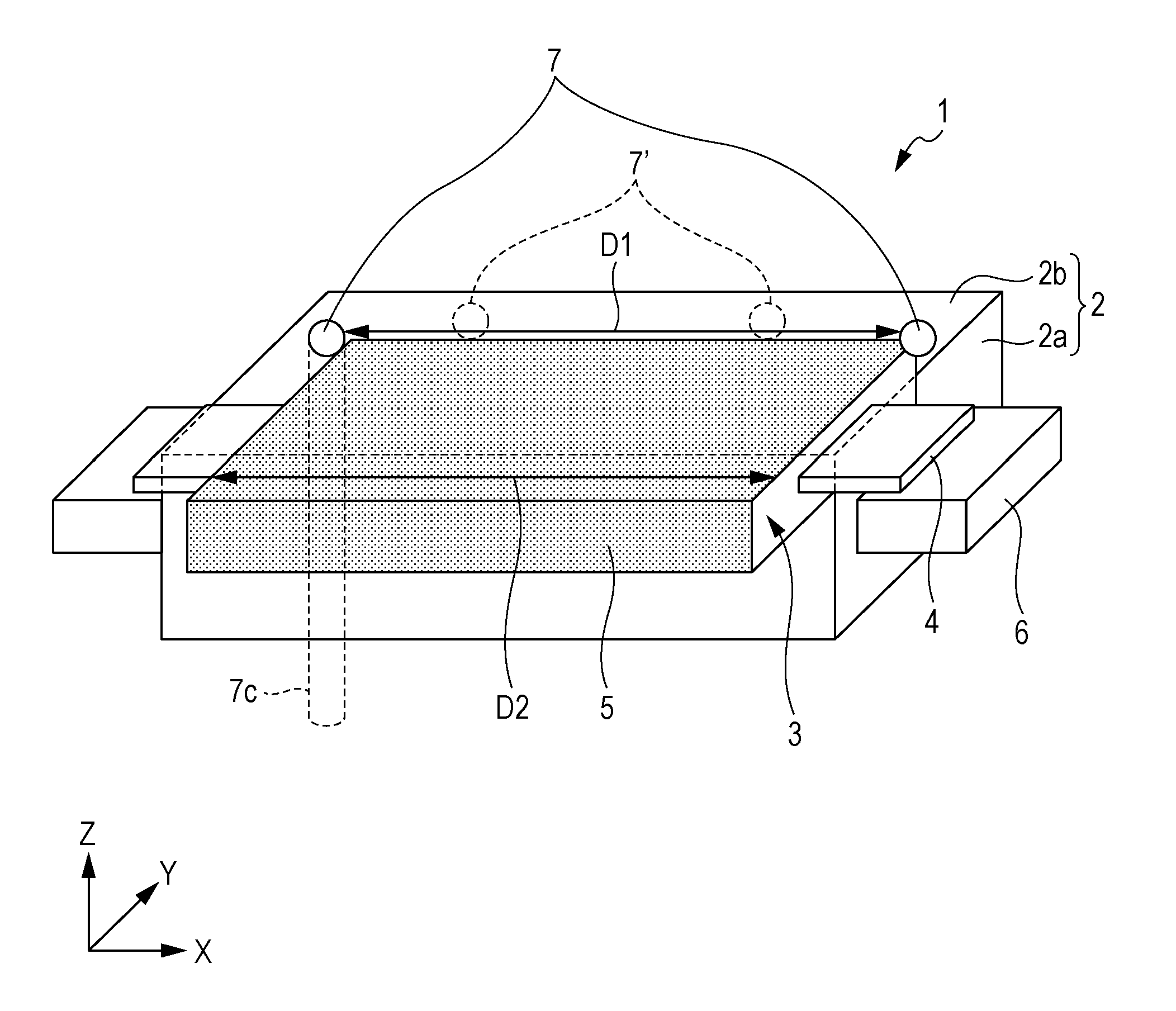
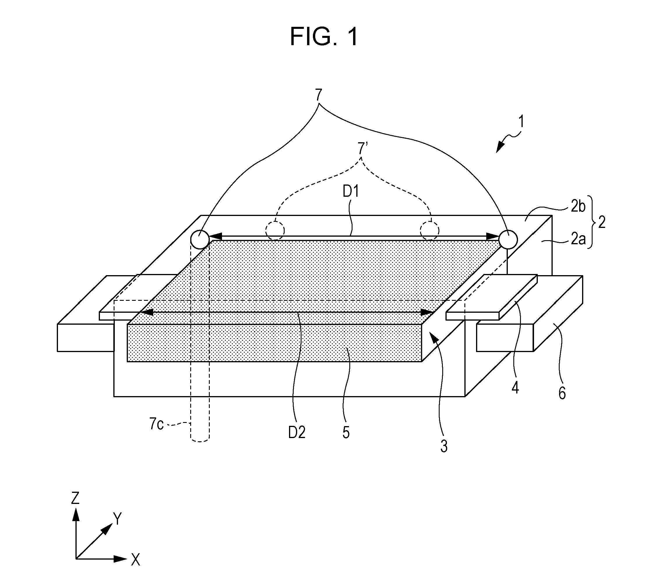
[0072]Furthermore, the filling was performed in a state where the battery can 2 was placed with the X-direction in FIG. 1 being oriented in the vertical direction (i.e., the direction of gravity).

[0073]When the battery can 2 was placed with the X-direction in FIG. 1 being oriented in the vertical direction, the two holes 7 were positioned at different heights and upper one of the two holes 7 was located at a higher position than the electrode laminate 3. The gas in the battery can 2 was exhausted through the upper hole 7, and the electrolyte was filled through the lower hole 7.

example 2

[0074]The following nonaqueous secondary battery (hereinafter referred to as a “nonaqueous secondary battery 1a”) was fabricated in accordance with the above-described method for fabricating the nonaqueous secondary battery.

[0075]More specifically, the nonaqueous secondary battery 1a had the same structure as the nonaqueous secondary battery 1 except that the heat shrinkable films 5 were omitted in the nonaqueous secondary battery 1a.

[0076]Furthermore, the filling was performed in a state where the battery can 2 was placed with the X-direction in FIG. 1 being oriented in the vertical direction.

example 3

[0077]The nonaqueous secondary battery 1a was fabricated in the same manner as that in EXAMPLE 2 in accordance with the above-described method for fabricating the nonaqueous secondary battery.

[0078]However, the filling was performed in a state where the battery can 2 was placed with the Z-direction in FIG. 1 being oriented in the vertical direction.


PUM


Abstract

At least one of holes is formed at a position that is at a higher level than a surface of an electrolyte in use of a nonaqueous secondary battery, and that is not overlapped with an electrode laminate.

Description

BACKGROUND OF THE INVENTION[0001]1. Field of the Invention[0002]The present invention relates to a nonaqueous secondary battery and a filling method for the nonaqueous secondary battery. It is to be noted that, in this specification, the term “filling” implies an operation of filling an electrolyte into a battery can of the nonaqueous secondary battery.[0003]2. Description of the Related Art[0004]For the purpose of smoothing the filling, there is proposed a technique of forming two holes in a battery can and filling an electrolyte through one of the two holes while exhausting gas (air) through the other hole such that the pressure in the battery can is reduced.[0005]Japanese Unexamined Patent Application Publication No. 10-241741 (publicized Sep. 11, 1998) discloses a technique of, for the purpose of smoothing the filling, forming a plurality of filling holes in a sealing member that seals off an exterior can, and filling an electrolyte through one of the filling holes while exhaust...

Claims


Application Information

Patent Timeline
IPC IPC(8): H01M2/36H01M50/618H01M50/627
CPCH01M2/36H01M10/0525H01M50/30H01M50/618H01M50/627Y02E60/10Y02P70/50
Inventor OHIRA, KOJIOKAMOTO
Owner SHARP KK
Why Eureka
Try Eureka