Casing Structure for Refrigeration System and Sealing Method for Refrigeration System Casing

a refrigeration system and sealing method technology, applied in the field of sealing method for refrigeration system casing, can solve problems such as air tightness drop, and achieve the effects of preventing leakage of sealant material, reducing filling time (sealing time), and high air tightness

Inactive Publication Date: 2009-05-28
DAIKIN IND LTD
View PDF5 Cites 9 Cited by
  • Summary
  • Abstract
  • Description
  • Claims
  • Application Information

AI Technical Summary

Benefits of technology

[0023]Therefore, in accordance with either the first or the fifth aspect of the present invention, it is arranged such that at least one end of the through hole (H) is covered over with the mesh member (31, 32). When sealant material is injected such that the through hole (H) is filled from the inside thereof with the injected material, the air present in the through hole (H) is purged out therethrough as the filling of the through hole (H) with sealant material progresses, while the injected sealant material is prevented, by the mesh members (31, 32), from flowing out from within the through hole (H). Accordingly, the through hole (H) is filled with sealant material without the creation of air gaps, thereby making it possible to provide sealing of high airtightness. Besides, the leakage of sealant material is prevented, thereby making it possible that the through hole (H) is filled with as much as the amount of sealant material actually injected thereinto, and the filling time (sealing time) can be reduced.
[0024]Especially, in accordance with the fourth aspect of the present invention, each opening end of the through hole (H) is covered over with the mesh member (31, 32). In this case, one of the mesh members (31, 32) is provided with a nozzle hole for insertion of the nozzle from which sealant material is injected such that the through hole (H) is filled from the inside thereof with the injected sealant material. This makes it possible to ensure that sealant material is injected in the middle of the through hole (H) while the injected sealant material is held back within the through hole (H) by each mesh member (31, 32).
[0025]In addition, in accordance with either the second or the sixth aspect of the present invention, the slit is provided so as to associate with the piping hole in the mesh member (31, 32), thereby making it possible to achieve easy mount of the mesh member (31, 32) over the opening end, even with the piping et cetera already inserted through the through hole (H). Accordingly, even in the case where, because of its complicated configuration, it is difficult to pass the piping into the through hole (H) after mounting the mesh member (31, 32) over the opening end, the piping et cetera can be passed into the through hole (H) before mounting the mesh member (31, 32). In other words, the workability of piping is enhanced.
[0026]Additionally, in accordance with either the third or the seventh aspect of the present invention, the mesh member (31, 32) is composed of a plurality of plies having respective slits formed and positioned so as not to overlap with each other, thereby making it possible to prevent the filled sealant material from flowing out by way of the slits. Therefore, it becomes possible to hold back the filled sealant material without fail while enhancing the workability of piping as described above.

Problems solved by technology

However, the problem with the seal method and the seal structure employed in the conventional refrigeration system is that it is likely that air bubbles and air gaps are created in a through hole (102), thereby leading to a drop in the airtightness.

Method used


Image

  • Casing Structure for Refrigeration System and Sealing Method for Refrigeration System Casing
  • Casing Structure for Refrigeration System and Sealing Method for Refrigeration System Casing
  • Casing Structure for Refrigeration System and Sealing Method for Refrigeration System Casing

Examples


Embodiment Construction

[0044]With reference to the drawings, an embodiment of the present invention is now described in detail below.

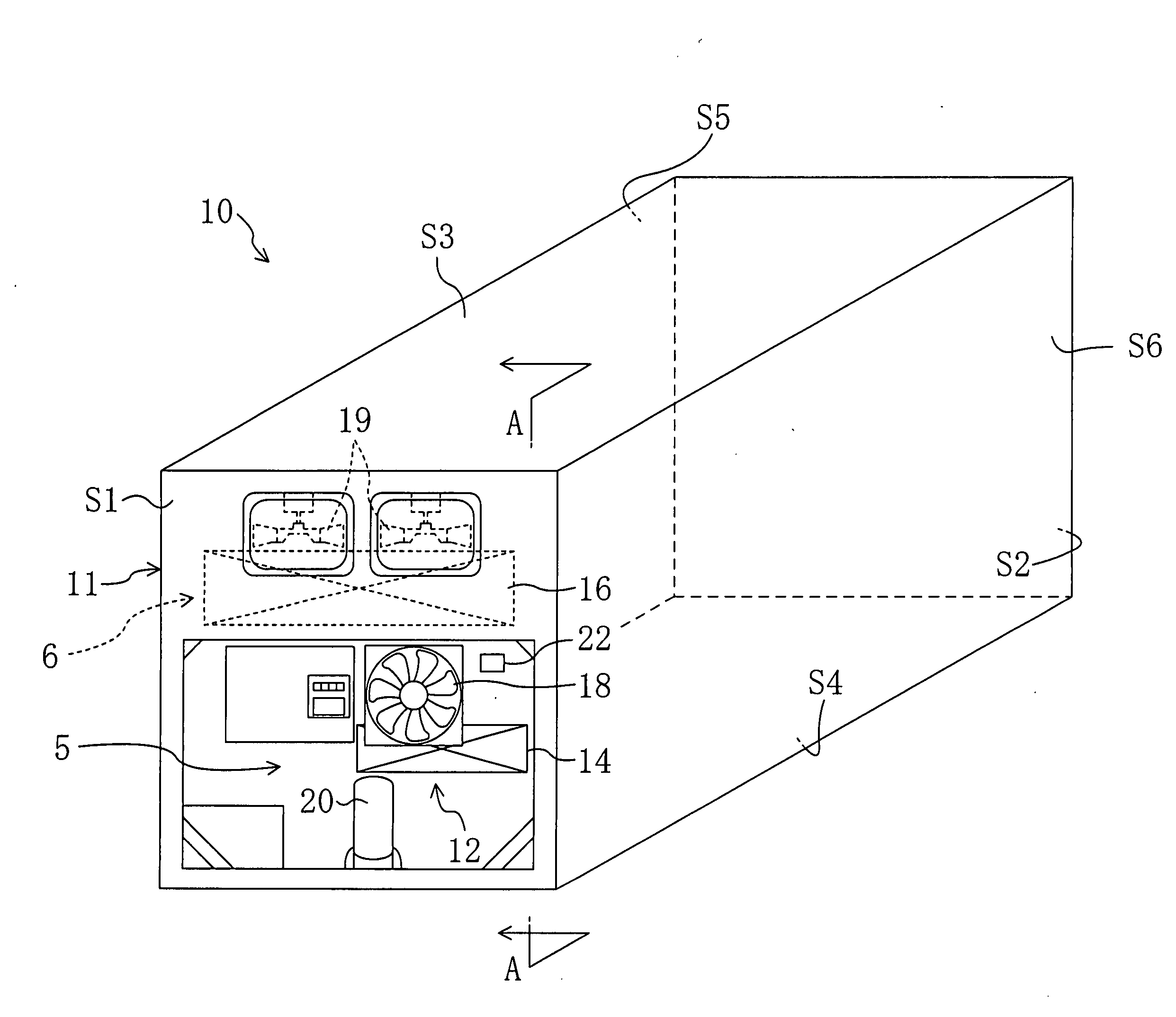
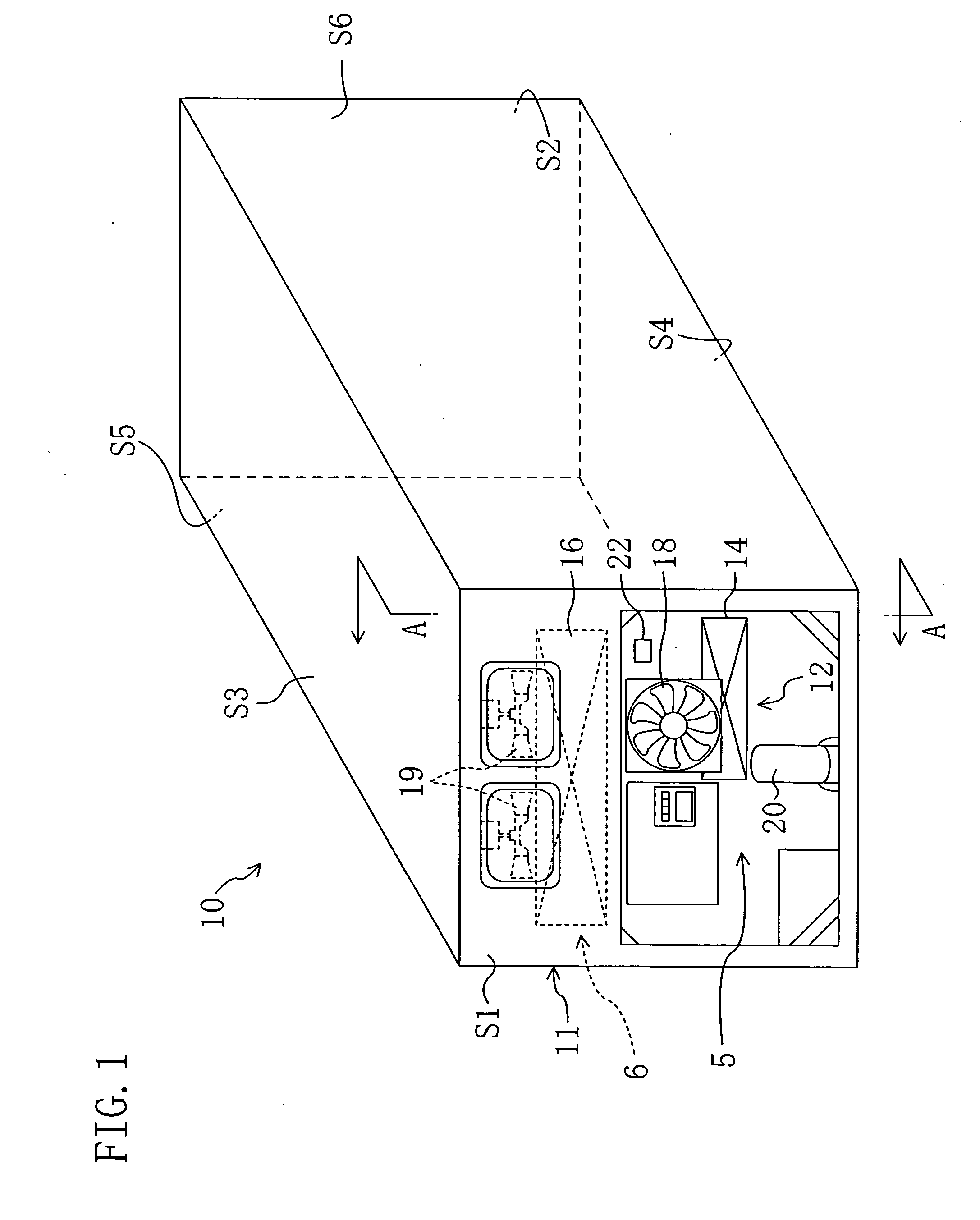
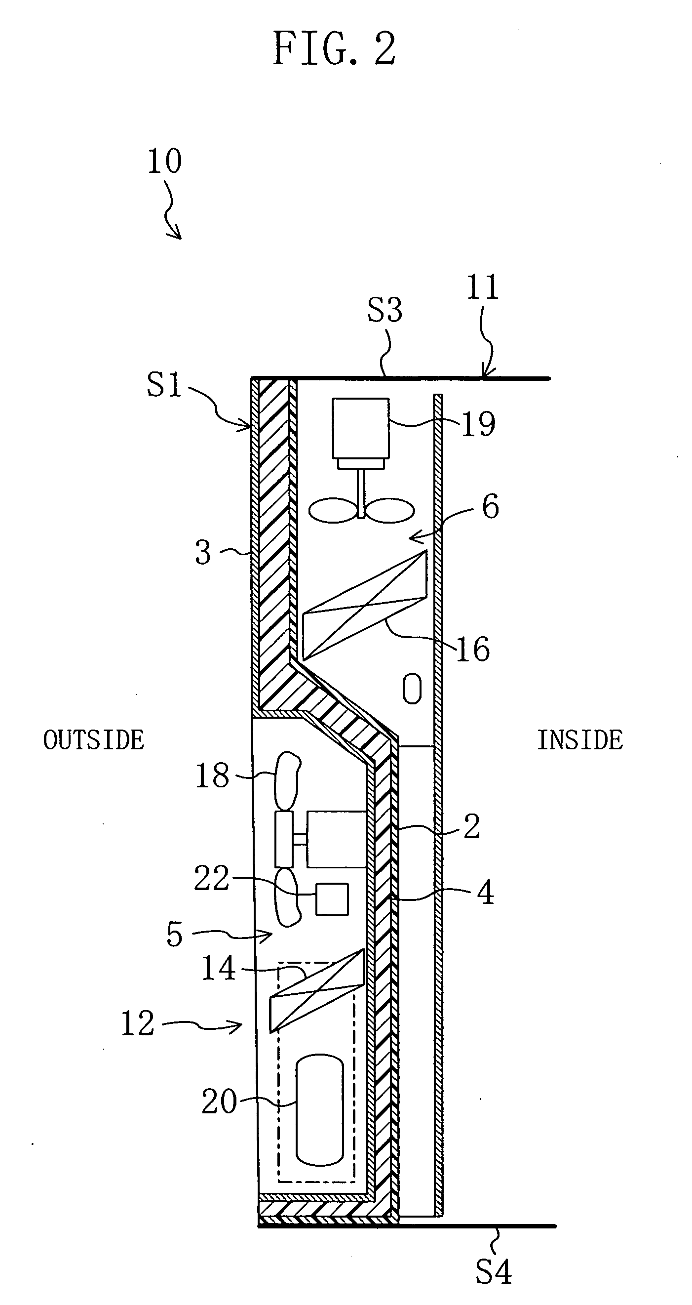
[0045]As shown in FIGS. 1 and 2, a freezing container (10) of the present embodiment is adapted for transportation by a container vessel or vehicle and its freight is kept cool during the transportation. The freezing container (10) includes a casing (11) having a compartment in which to contain freight, and a refrigeration system (12) operable to provide cooling of the inside (compartment) of the casing (11).

[0046]The casing (11) has a front side panel (S1), a rear side panel (S2), a top side panel (S3), a bottom side panel (S4), a left-hand side panel (S5), a right-hand side panel (S6). The casing (11) is formed substantially in the shape of a rectangular parallelepiped. Note that, in FIG. 1, the near side is the front side, the far side is the rear side, and the direction of right and left is the direction when viewed from the front side.

[0047]Each of the panels (S1) to (S...


PUM

PropertyMeasurementUnit
thickaaaaaaaaaa
thickaaaaaaaaaa
sizeaaaaaaaaaa

Abstract

A casing (11) for use in a freezing container is provided with a through hole (H) for insertion of the piping of a refrigerant circuit therethrough. Each opening end of the through hole (H) is covered over with a respective mesh sheet (31, 32). With each opening end of the through hole (H) covered over with the mesh sheet (31, 32), the tip end of a filling nozzle (33) is inserted until it reaches the middle of the through hole (H) and a sealant material is injected. The injected sealant material is held back within the through hole (H) by each mesh sheet (31, 32) and, with the progress of the injection of the sealant material, the air present in the through hole (H) is purged out through each mesh sheet (31, 32).

Description

TECHNICAL FIELD[0001]The present invention relates to a casing structure for a refrigeration system and to a sealing method for a refrigeration system casing. More specifically, this invention relates to a technology capable of providing sealing of enhanced airtightness.BACKGROUND ART[0002]In the past, freezing containers, such as one disclosed, for example, in JP-A-H08 (1996)-337285, for use in marine transport or other transport have been known in the art. This type of freezing container includes a container casing having therein a freight compartment and a refrigeration system for providing cooling of the freight compartment.[0003]The refrigeration system includes a refrigerant circuit formed by connecting, by refrigerant piping, a compressor, a condenser, an evaporator, et cetera, and a thermal insulation casing which provides separation between the freight compartment of the container casing (the inside of the container casing) and the outside of the container casing. The compr...

Claims


Application Information

Patent Timeline
Patent Type & Authority Applications(United States)
IPC IPC(8): F25D23/00F25B1/00B23P19/04
CPCB60H1/00514F16L5/02Y10T29/53F25D19/003F25D23/068F16L5/14
Inventor KITAMURA, YOSHINORIOSHITANI, MITSUHIRO
Owner DAIKIN IND LTD
Why Eureka
Try Eureka