Method for producing polymeric optical waveguide and device for producing the same

a technology of optical waveguides and polymeric optical waves, which is applied in the direction of dough shaping, manufacturing tools, instruments, etc., can solve the problems of high cost of methods (2) and (3), accuracy of core diameter, and low cost of polymeric opticals, so as to reduce waveguide loss and high precision. , the effect of low cos

Inactive Publication Date: 2005-01-27
FUJIFILM BUSINESS INNOVATION CORP
View PDF21 Cites 9 Cited by
  • Summary
  • Abstract
  • Description
  • Claims
  • Application Information

AI Technical Summary

Benefits of technology

[0017] The inventors of the invention have found a production method which not only can shorten filling time but is also free from waveguide defects in producing a polymeric optical waveguide with reduced waveguide loss and insertion loss while precisely maintaining a core shape by utilizing a capillary phenomenon, which method has been proposed by the inventors.
[0018] A method has been proposed in which a curable resin is introduced from an end of a concave portion on one side of a branch of a mold corresponding to a branched waveguide toward an outlet from which the resin is sucked on the other side of the branch and, at the same time, a concave end which is not an inlet is closed to thereby prevent air from being confined in the inside of the filled resin whereby not only filling time is shortened by using suction even in a branched waveguide but also the introduction of air to the resin is prevented.
[0021] According to the invention, a highly precise polymeric optical waveguide with reduced waveguide loss can be produced by a simple method at low cost and a flexible polymeric optical waveguide which is excellent in mass-productivity and has a high degree of freedom can be produced. In particular, in the case of an waveguide having a branched structure, not only filling time can be shortened by using suction but also an waveguide free from any defects can be produced.

Problems solved by technology

However, the selective polymerization method (1) has a problem in lamination of the film, methods (2) and (3) are expensive because a photolithographic method is used, and method (4) has a problem in accuracy of a core diameter.
Also, method (5) has a problem in that a sufficient difference between the refractive index of the core layer and that of the clad layer cannot be obtained.
However, none of these methods are suitable for the formation of a polymeric optical waveguide on a flexible plastic substrate having a large area.
However, this method has a problem in that not only the capillary groove is filled with the polymer precursor material but also the polymer precursor material spreads the entire surface of the pattern substrate and the polymer precursor material of the surface of the pattern substrate is also cured to form a thin layer having the same composition as the core layer, resulting in light leaking through this thin layer.
However, this method is complicated because if the clamp is not used to bring the pattern substrate into close contact with the plane substrate, the monomer solution also enters parts other than the core and therefore a precise waveguide structure cannot be formed.
This method has another drawback in that the volume Of the monomer solution changes when undergoing polymerization to form a macromolecule (solidification), leading to change in a core shape.
Moreover, still another drawback is that the core shape collapses at the time of removal of the capillary because a polymer obtained by the polymerization of the monomer solution is partially brought into close contact with the capillary.
However, the production method described in this patent is unsuitable for mass-production since a long period of time is required to form a core of an optical waveguide, the sectional area of which core is small.
This method also has a drawback in that the volume of the monomer solution changes when the monomer solution is reacted and solidified, causing change in the core shape and increased transmission loss (waveguide loss).
In this method, much time may be required to fill space for a core with a core-forming curable resin to form a core, particularly a long core, leading to low productivity.
However, plural branched filling ports must be removed by precise processing to produce an waveguide having a desired shape, which leads to increased costs and also causes increased waveguide loss depending on the processing accuracy.
However, if this method is applied to the formation of an waveguide having a branched structure, a part of a core cannot be well filled and, when the resin is sucked, air may be introduced to the resin, forming an waveguide with a formed core having defects.

Method used


Image

  • Method for producing polymeric optical waveguide and device for producing the same
  • Method for producing polymeric optical waveguide and device for producing the same
  • Method for producing polymeric optical waveguide and device for producing the same

Examples


example 1

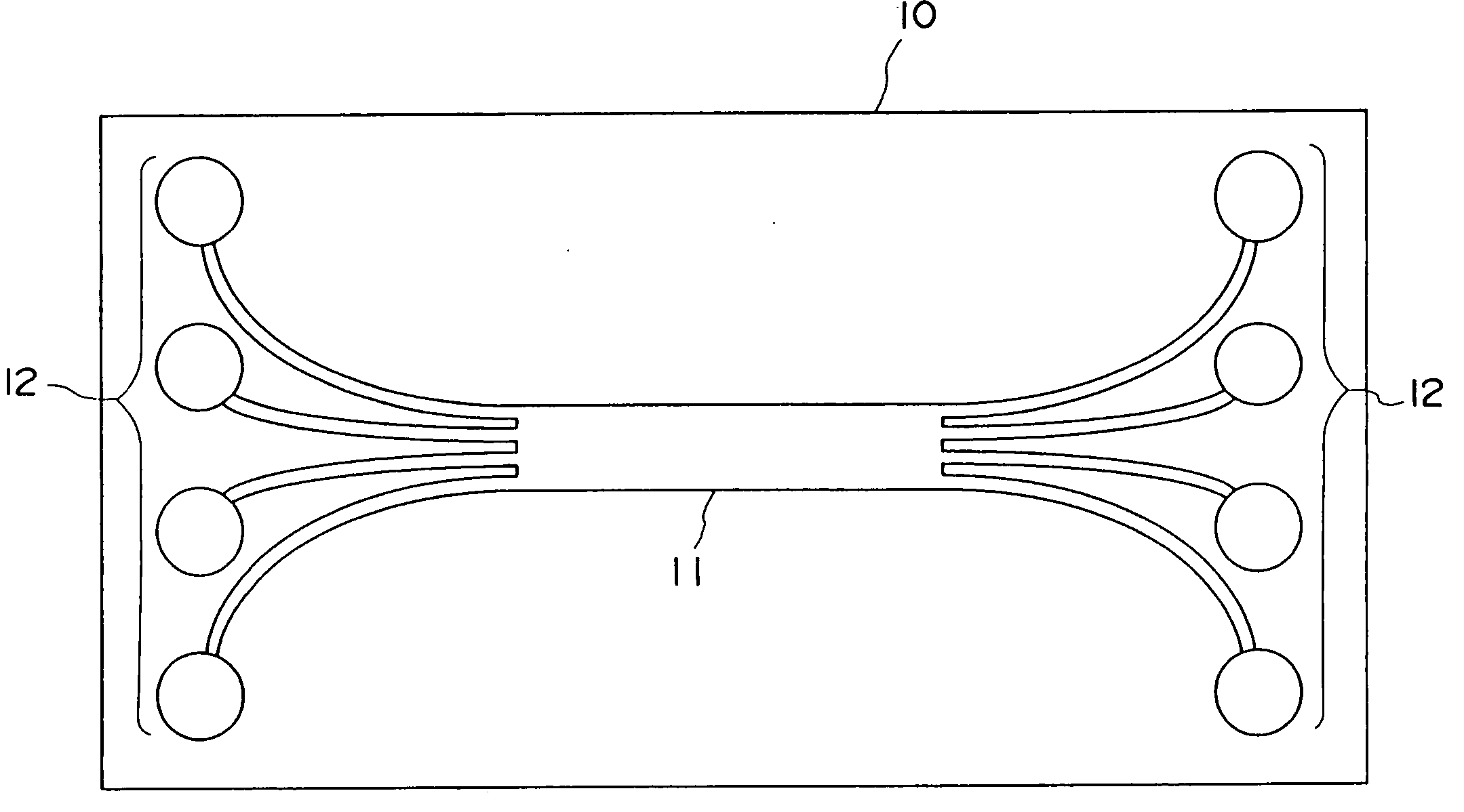
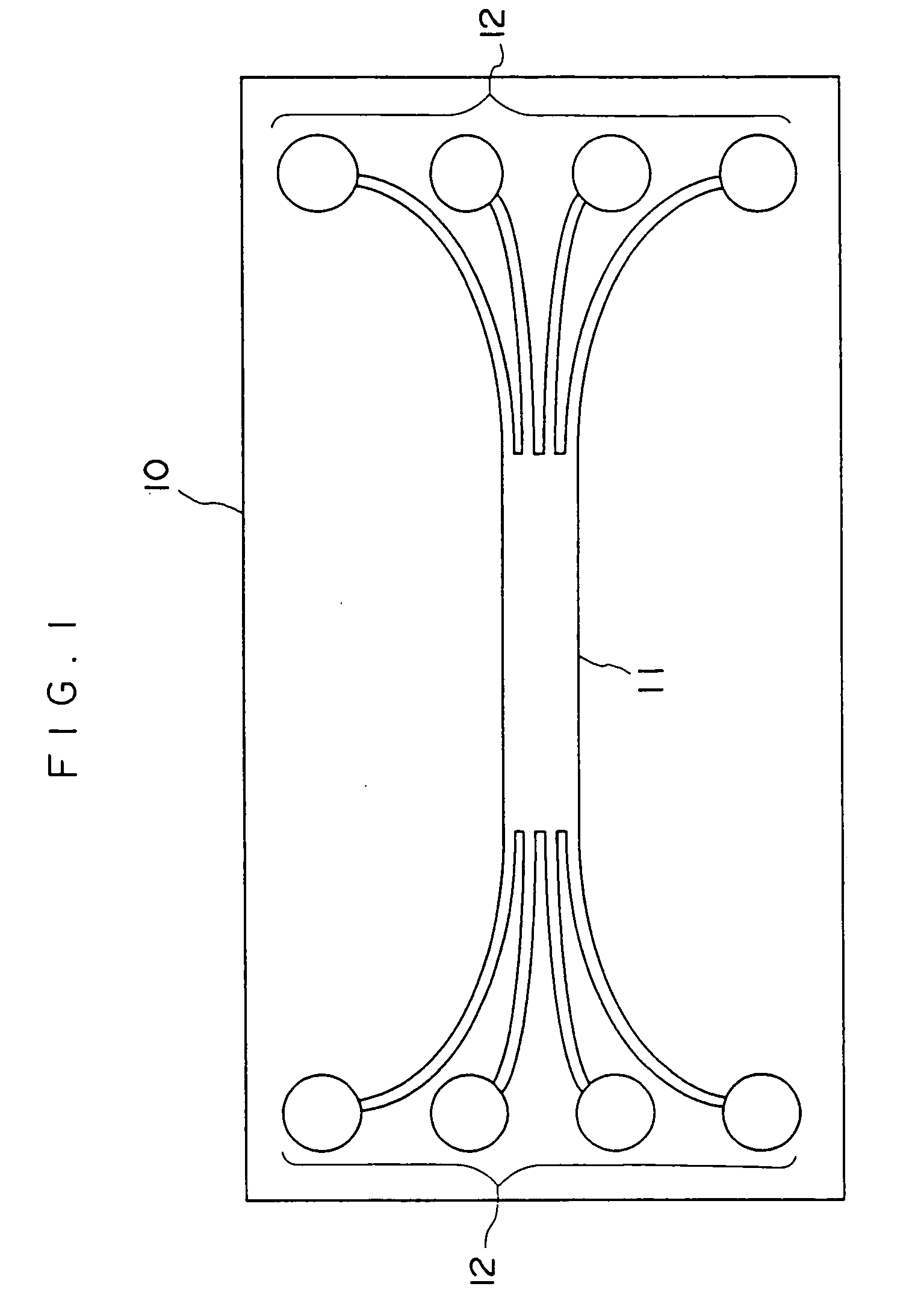
[0132] A thick film resist (SU-8, manufactured by Microchem Inc.) is applied to the surface of a silicon substrate having a diameter of 6 inch by a spin coating method. Then, the thick film resist is pre-baked at 80° C., subjected to pattern exposure through a photomask, and developed to form a convex portion having a length of 8 cm. Next, the developed film is post-baked at 120° C. to produce a master plate for forming an optical waveguide core. The master plate has a convex portion corresponding to a 4×4 type star coupler and having a total length of 6 cm. The convex portion has a branch junction and branched portions. The branch junction has a length of 3 cm and the cross-section of each of the branched portions is a 50 μm×50 μm square.

[0133] After n-hexane is applied to the surface of the master plate having the convex portion as a releasing agent, a thermosetting polydimethylsiloxane (PDMS) elastomer (SYLGARD 184, manufactured by Dow Corning Asia) is flowed into the master pla...

example 2

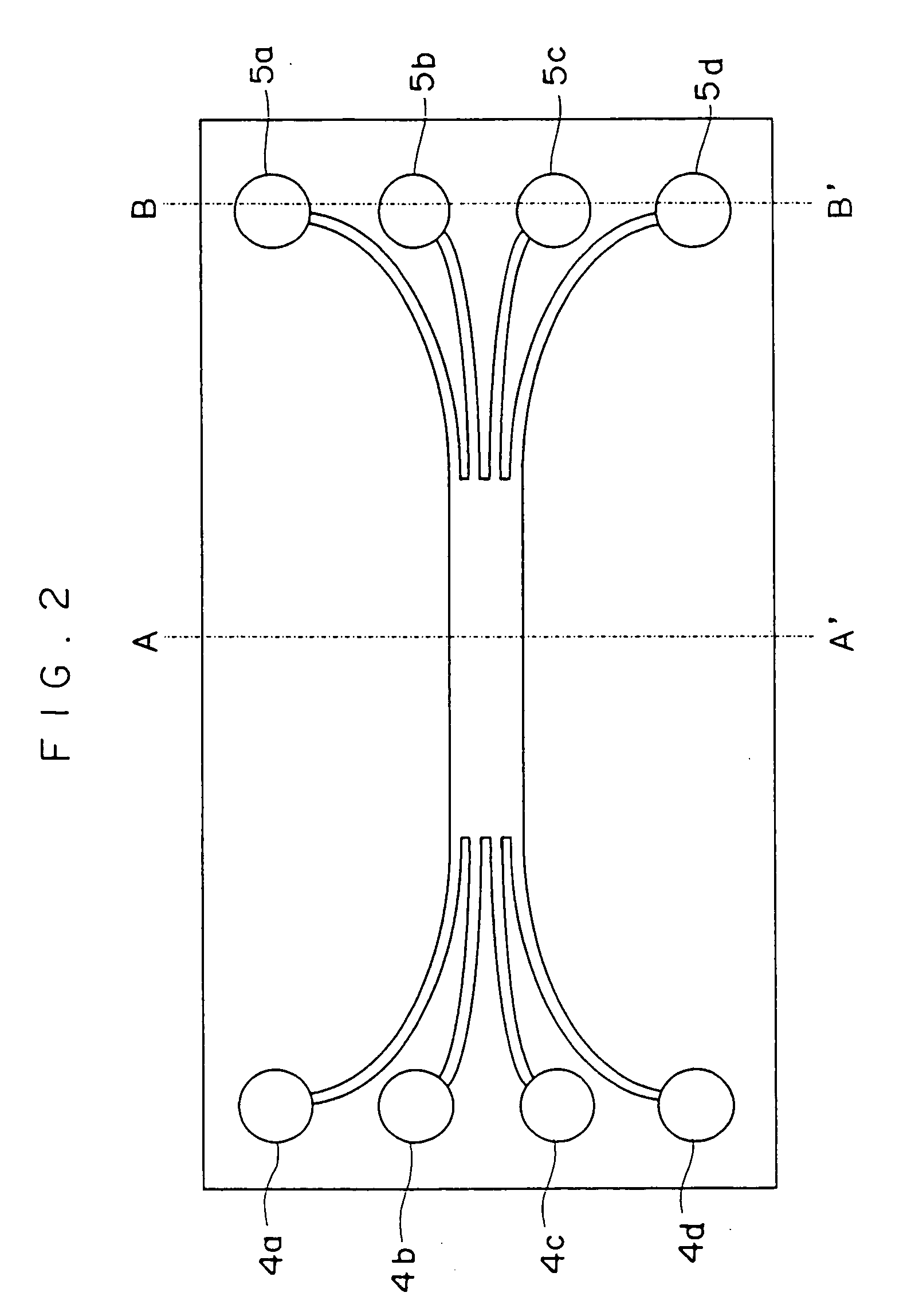
[0141] A mold shown in FIG. 10 is prepared in the same manner as the preparation of the mold used in Example 1, except that a cylindrical through-hole having a diameter of 3 mm is formed at each end of the mold. As a result, two through-holes are formed in total and each through-hole communicates with four branched portions formed at the same end of the branch junction. Thus, the outer end of each branched portion communicating with the corresponding through-hole is a concave end.

[0142] Next, one concave end (one of concave ends communicating with the through-hole 4a shown in FIG. 2) is used as a resin inlet. The concave end is referred to as a concave end X hereinafter. Moreover, a dispenser which has the same structure of the resin supply unit shown in FIG. 9 is used for introducing the resin. The dispenser has a fitting portion which can be fit into the through-hole. The fitting portion has a resin outlet corresponding to the concave end X which serves as the resin inlet. The fi...


PUM

PropertyMeasurementUnit
diameteraaaaaaaaaa
diameteraaaaaaaaaa
edge lengthaaaaaaaaaa

Abstract

The present invention relates to a method for producing a polymeric optical waveguide, comprising: preparing a mold having, on a surface thereof, a branched concave portion for forming a core; bringing a clad substrate into close contact with the surface of the mold having the branched concave portion; filling the branched concave portion with a core-forming curable resin by supplying and sucking the core-forming curable resin from one end of the branched concave portion into the branched concave portion toward another end of the branched concave portion which is provided opposite the one end while the remaining ends of the branched concave portion are closed, by opening the closed ends, and by sucking the core-forming curable resin into portions communicating with the opened ends; and curing the core-forming curable resin; and a production device used for the above method.

Description

CROSS-REFERENCE TO RELATED APPLICATION [0001] This application claims priority under 35 U.S.C. 119 from Japanese Patent Application No. 2003-277466, the disclosure of which is incorporated by reference herein. BACKGROUND OF THE INVENTION [0002] 1. Field of the Invention [0003] The present invention relates to a method and a device for producing at low cost a polymeric optical waveguide, and particularly a flexible polymeric optical waveguide. [0004] 2. Description of the Related Art [0005] In producing a polymeric optical waveguide, the following methods have been proposed: (1) a method in which a film is impregnated with a monomer, and the core portion is selectively exposed to light to change the refractive index in the portion and the film is then laminated on a substrate (selective polymerization method), (2) a method in which a core layer and a clad layer are applied to a substrate and then a clad portion is formed by using reactive ion etching (RIE method), (3) a method using ...

Claims


Application Information

Patent Timeline
Patent Type & Authority Applications(United States)
IPC IPC(8): B29C31/04G02B6/13B29C35/08B29D11/00
CPCB29C31/04B29L2011/0075B29D11/00663B29C2035/0827
Inventor SHIMIZU, KEISHIOHTSU, SHIGEMIYATSUDA, KAZUTOSHIAKUTSU, EIICHI
Owner FUJIFILM BUSINESS INNOVATION CORP
Why Eureka
Try Eureka