High-speed bulk filling tank truck

a tank truck and high-speed technology, applied in the direction of liquid handling, container discharging methods, packaging goods, etc., can solve the problems of reducing the filling time, reducing the operating rate, and increasing the risk of accidents

Inactive Publication Date: 2005-05-10
KOOA GASU KAGOSHIMA
View PDF1 Cites 8 Cited by
  • Summary
  • Abstract
  • Description
  • Claims
  • Application Information

AI Technical Summary

Benefits of technology

[0014]According to the invention, therefore, it is possible to recover the gas in the filling hose and the leading end of the recovery hose into the gas recovery container prior to cutting off from th

Problems solved by technology

However, the conventional tank truck described above has a problem of a long filling time of the liquefied gas into the bulk storage tank, and there has been a demand for reducing the filling time.
The filling operation of the tank truck is carried out by vi

Method used


Image

  • High-speed bulk filling tank truck
  • High-speed bulk filling tank truck
  • High-speed bulk filling tank truck

Examples


Embodiment Construction

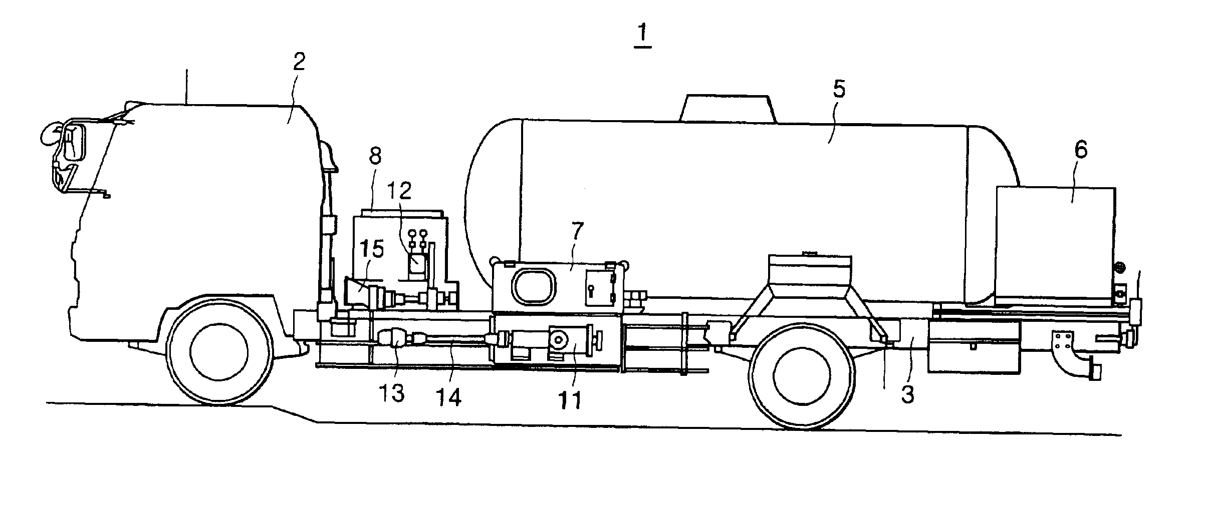
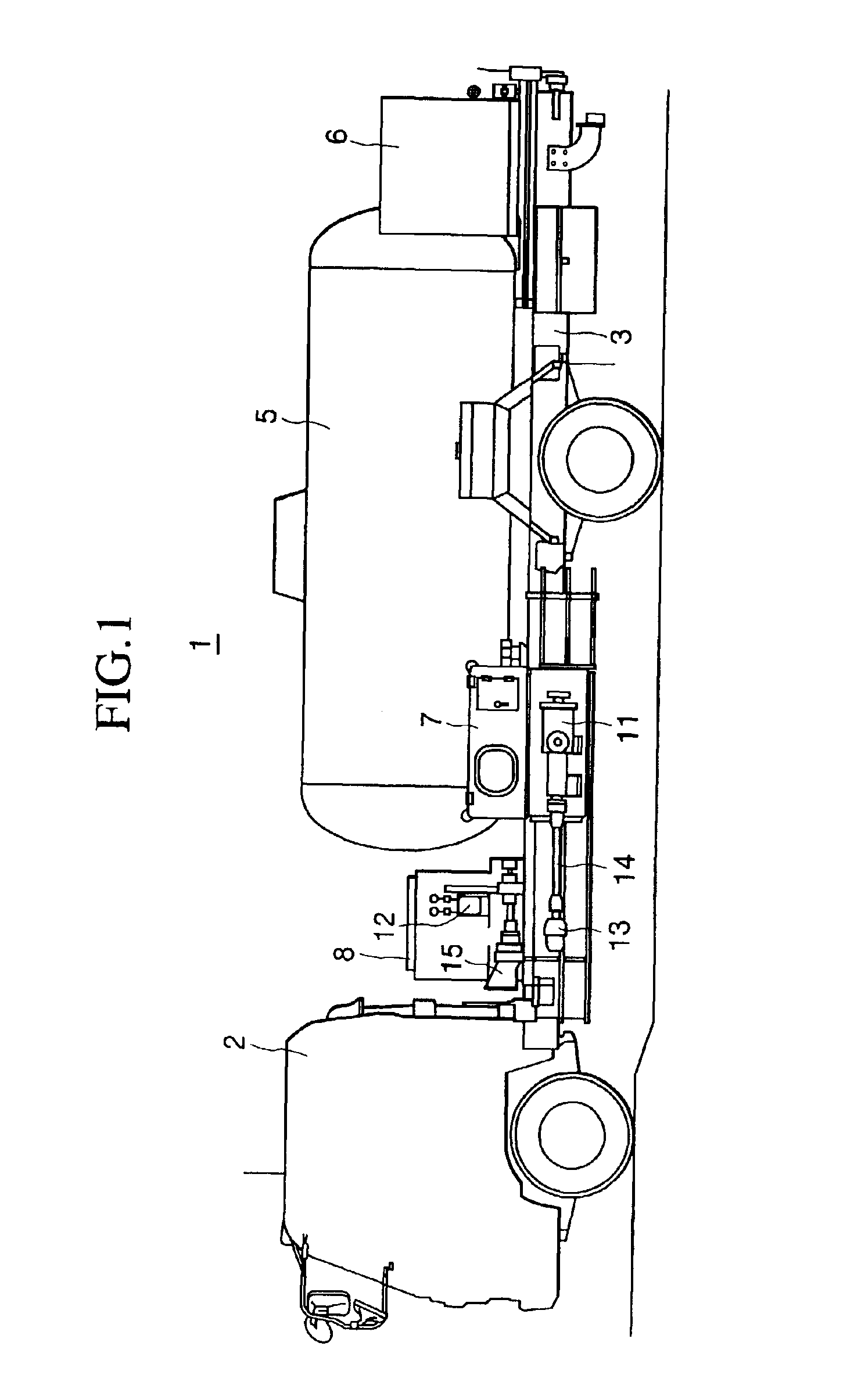
[0026]Embodiments of the high-speed bulk filling tank truck of the present invention will now be described with reference to the drawings. FIG. 1 is a side view, partial schematic representation of a first embodiment of the high-speed bulk filling tank truck. On the high-speed bulk filling tank truck 1, a truck tank 5 is mounted on a chassis 3 of a running vehicle 2, and the truck tank 5 is connected to various valves and meters, or to a filling hose and a recovery hose housed in a hose reel box 6 on the rear end via liquid feeding means. A fluid circuit having piping, valves and meters fills a bulk storage tank with liquefied gas. The fluid circuit has a liquid line and a gas line for receiving the liquefied gas from a supply terminal into the truck tank 5, and has valves and meters housed in a valve / instrument box 7.

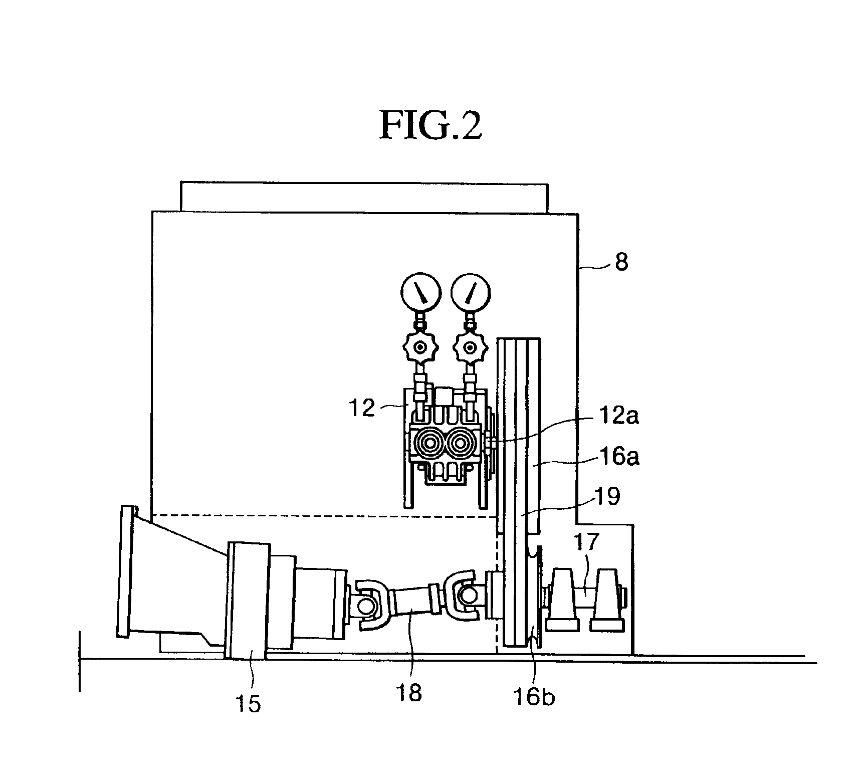
[0027]A gas compressor 12 is used in this embodiment in addition to the liquid feed pump 11, on the fluid circuit as described above, as liquid feeding means for filli...


PUM

PropertyMeasurementUnit
Internal pressureaaaaaaaaaa

Abstract

A high-speed bulk filling tank truck is provided, which permits reduction of the filling time. The high-speed bulk filling tank truck delivers a liquefied gas in a truck tank to a bulk storage tank, and recovers a gas-phase gas in the bulk storage tank into the truck tank, thereby filling the bulk storage tank with the liquefied gas. The high-speed bulk filling tank truck includes a liquid feed pump, provided on a liquid line through which the liquefied gas flows, for feeding the liquefied gas in the truck tank to the bulk storage tank, and a gas compressor, provided on the gas line through which a gas-phase gas flows, for compressing the gas-phase gas in the bulk storage tank and delivering the same into the truck tank.

Description

BACKGROUND OF THE INVENTION[0001]The present invention relates to a high-speed bulk filling tank truck for filling a bulk storage tank with a liquefied gas. More particularly, the invention relates to a high-speed bulk filling tank truck permitting reduction of the filling time.[0002]In place of the conventional practice to supply liquefied gas in gas bottles, another practice of direct supply is now becoming more popular, which comprises installing installation-type bulk storage tanks having a large capacity in general houses and plants, and transporting the liquefied gas on small-sized trucks known as tank trucks to directly fill the bulk storage tanks. The tank truck used for filling the liquefied gas has a tank (the “truck tank”) for loading the liquefied gas on the chassis of a running vehicle. A filling hose and an equalizing hose are connected to the truck tank via a liquid / gas line, in which devices for liquid such as various valves and meters are arranged. According to this...

Claims


Application Information

Patent Timeline
IPC IPC(8): B60P3/22F17C5/00F17C13/00F17D1/08
CPCB60P3/2245F17C5/02F17C5/007F17C2270/0171F17C2201/0109F17C2201/035F17C2201/054F17C2205/0326F17C2205/037F17C2205/0385F17C2223/0153F17C2223/033F17C2227/0135F17C2227/0157F17C2227/04F17C2250/072F17C2260/025Y10T137/3109Y10T137/6881
Inventor KAMIKOZURU, MASAYASU
Owner KOOA GASU KAGOSHIMA
Why Eureka
Try Eureka