Paint Roller

a technology of paint rollers and rollers, which is applied in the direction of shafts and bearings, coatings, artistic surface treatment, etc., can solve the problems of inconvenient manufacturing, inconvenient operation, and inability to meet the needs of the user, and achieve the effect of convenient manufacturing

Inactive Publication Date: 2014-01-30
PERREAULT DANIEL
View PDF10 Cites 11 Cited by
  • Summary
  • Abstract
  • Description
  • Claims
  • Application Information

AI Technical Summary

Benefits of technology

[0022]Advantageously, the proposed paint roller conveniently and securely prevents a roller cover from being longitudinall

Problems solved by technology

The paint rollers of the prior art generally become gradually inefficient for retaining a roller cover on their cage assembly as their retaining mechanism becomes more and more soaked in wet paint.
Also, to engage or release a roller cover onto or from the roller cage as

Method used


Image

  • Paint Roller
  • Paint Roller
  • Paint Roller

Examples


Embodiment Construction

[0031]In this document, the terminology “substantially” is used to denote variations in the thus qualified terms that have no significant effect on the principle of operation of the invention. These variations may be minor variations in design or variations due to mechanical tolerances in manufacturing and use of the various components of the invention. These variations and their effects are to be understood from the point of view of a person skilled in the art to which the present invention relates.

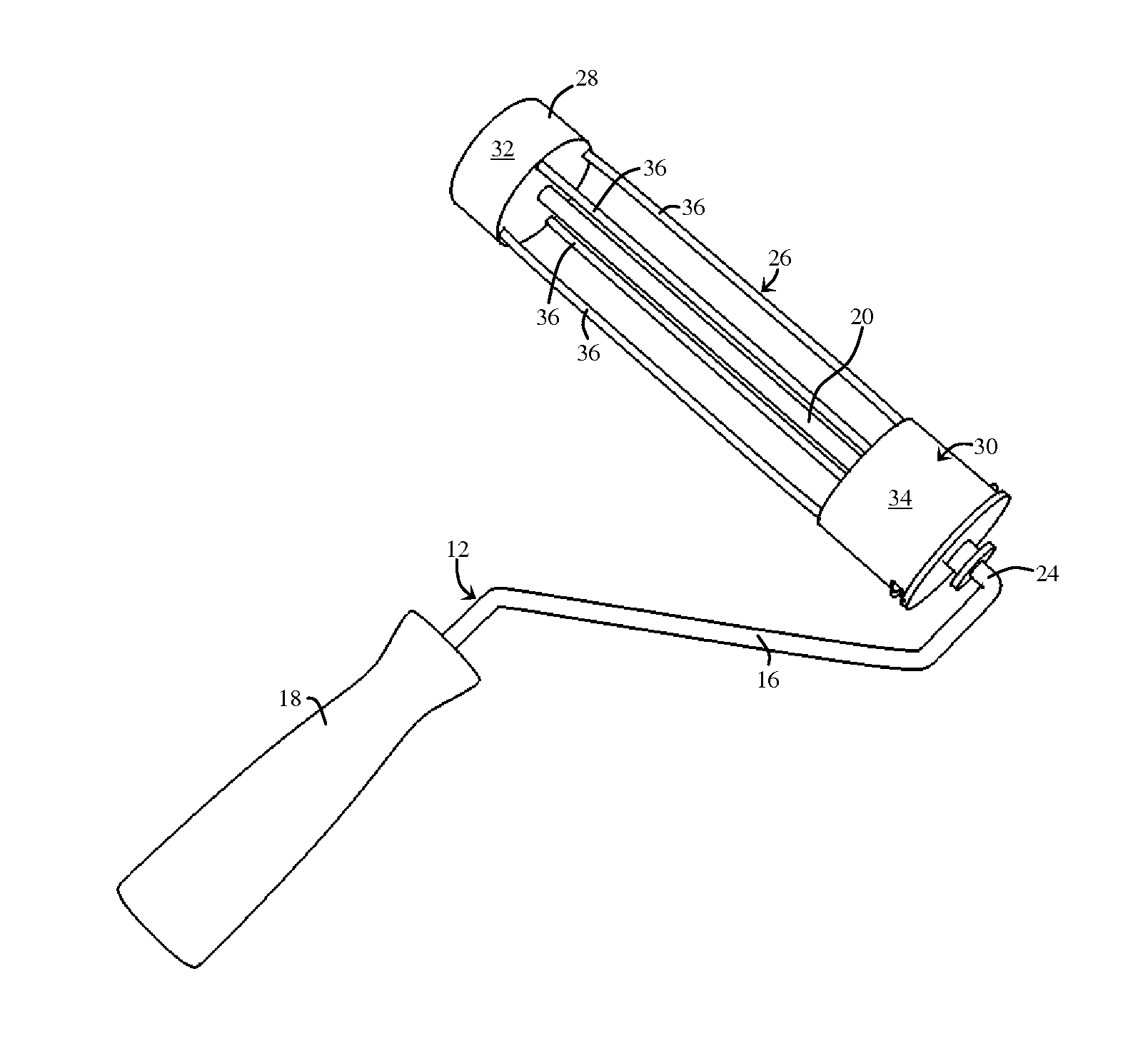
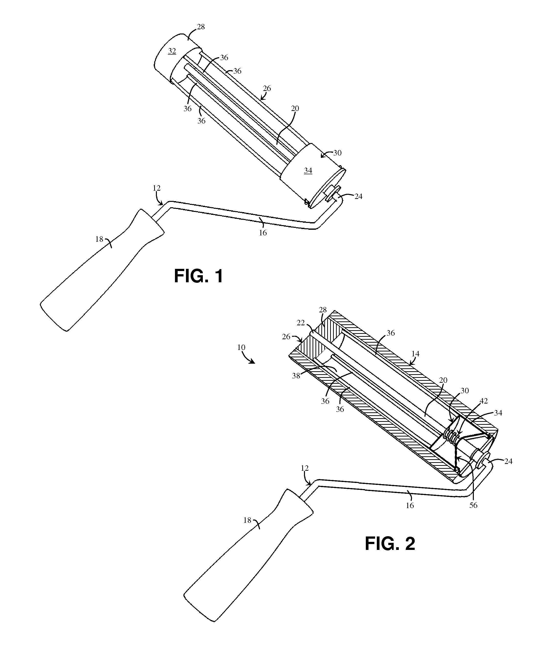
[0032]In FIGS. 1 to 5 show various aspects of an embodiment of a paint roller 10 in accordance with an embodiment of the present invention. Now referring more particularly to FIG. 2, the paint roller 10 generally includes a paint roller support 12 and at least one roller cover 14 (both shown assembled in a perspective cross-sectional view in FIG. 2). The paint roller support 12 includes a frame 16 and a roller cage assembly 26 rotatably mounted to the frame 16. The roller cover 14 is rem...


PUM


Abstract

A paint roller comprising: a frame; a roller cage assembly rotatably mounted to the frame; and a roller cover removably mountable to the roller cage assembly, the roller cover defining a roller cover passageway. The roller cage assembly includes a hub for mounting the roller cover thereonto, the hub defining a hub outermost surface insertable in the roller cover passageway and a locking mechanism for selectively locking the roller cover, the locking mechanism including a locking element movable between a locking position and a releasing position, the locking element defining a protruding portion. In the locking position, the protruding portion protrudes from the hub outermost surface. In the releasing position, the protruding portion is retracted inwardly relative to the hub outermost surface.

Description

FIELD OF THE INVENTION[0001]The present invention relates generally to paint rollers and, more particularly, to a paint roller having a locking mechanism for locking a paint roller cover thereto.BACKGROUND[0002]The prior art proposes numerous paint rollers provided with special means for securing the position of a roller cover onto the rotatable portion, also commonly known as the roller cage assembly, of the paint roller. These specially equipped paint rollers of the prior art have been designed to avoid a common annoying situation with conventional paint rollers wherein the roller cover has a tendency to gradually slip out of the roller cage assembly during a paint job.[0003]While these prior art paint rollers can generally fulfill the main objective of preventing the roller cover from slipping out of the cage assembly, they also entail one or more of the following disadvantages. The paint rollers of the prior art generally become gradually inefficient for retaining a roller cover...

Claims


Application Information

Patent Timeline
IPC IPC(8): B05C17/02
CPCB05C17/0217B05C17/0207
Inventor PERREAULT, DANIEL
Owner PERREAULT DANIEL
Why Eureka
Try Eureka