Measuring Apparatus, Particularly Measuring Apparatus for Sensing Metal Articles

a technology of measuring apparatus and metal objects, which is applied in the direction of instruments, material magnetic variables, and reradiation, etc., can solve the problems of adverse effects on the exact determination of the location and/or the borders of the metal object, and the sensitivity of the metal detector, so as to achieve the effect of improving the utilization of the dynamic range of the measuring apparatus, over-control of the reception amplifier, and improving the utilization of the dynamic rang

Active Publication Date: 2014-01-30
ROBERT BOSCH GMBH
View PDF5 Cites 2 Cited by
  • Summary
  • Abstract
  • Description
  • Claims
  • Application Information

AI Technical Summary

Benefits of technology

[0007]The root mean square value of the transmission voltage can be more easily influenced than the frequency of said transmission voltage, and therefore the measuring apparatus can be of relatively simple design.
[0009]It is particularly simple to influence the pulse width of a signal with a fixed frequency and this can advantageously be carried out by means of a low-power programmable microcomputer. At the same time, the programmable microcomputer can be used for further control tasks within the measuring apparatus, with the result that a highly efficient design of a metal detector can be achieved. In a particularly preferred embodiment, the signal is a square-wave signal and no further components are provided for converting the square-wave signal into an approximately sinusoidal signal at the transmission coil.
[0010]The control device can be designed to change the root mean square value of the transmission voltage depending on the reception voltage. As a result, the dynamic range of the measuring apparatus can be extended, this being largely transparent to a user of the measuring apparatus. In a further embodiment, the change in the sensitivity is compensated for, for example, in a calculated manner within the control device, with the result that the change in sensitivity is partly or completely compensated for in the value which is output by means of the output device.
[0012]The extension of the dynamic range of the measuring apparatus can be made even more transparent; overcontrol of the reception amplifier can additionally be avoided, as a result of which improved utilization of the dynamic range of the measuring apparatus can be made possible and an achievable degree of accuracy with which the metal article is determined can be improved.
[0013]In a first variant, the root mean square value of the transmission voltage can be continuously changed. Simpler operability of the measuring apparatus can be supported as a result. In a second variant, the root mean square value of the transmission voltage can be changed in discrete steps. Certain variants for influencing the root mean square value of the transmission voltage can be simply implemented by virtue of limiting to discrete stages of the transmission voltage.

Problems solved by technology

However, a large metal article and / or a metal article which is close to the coils can in this case lead to a reception voltage which overcontrols the amplifier.
Exact determination of the location and / or the borders of the metal article can be adversely affected by such a great sensitivity of the metal detector.
However, frequency adjustment of this kind requires complex circuitry and, in the case of implementation by means of a programmable microcomputer, may require a relatively powerful processing unit.
Manufacturing costs of the metal detector may be increased in both variants.

Method used


Image

  • Measuring Apparatus, Particularly Measuring Apparatus for Sensing Metal Articles
  • Measuring Apparatus, Particularly Measuring Apparatus for Sensing Metal Articles
  • Measuring Apparatus, Particularly Measuring Apparatus for Sensing Metal Articles

Examples


Embodiment Construction

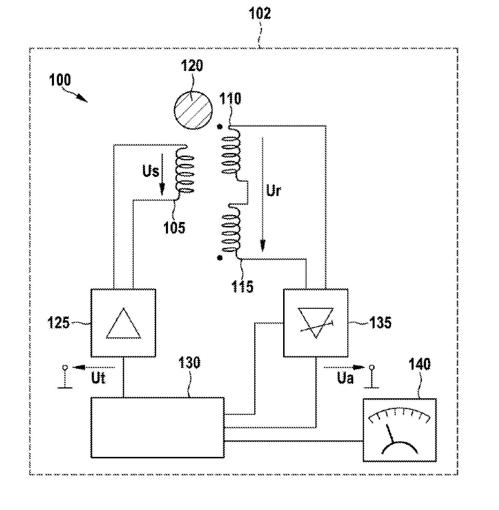
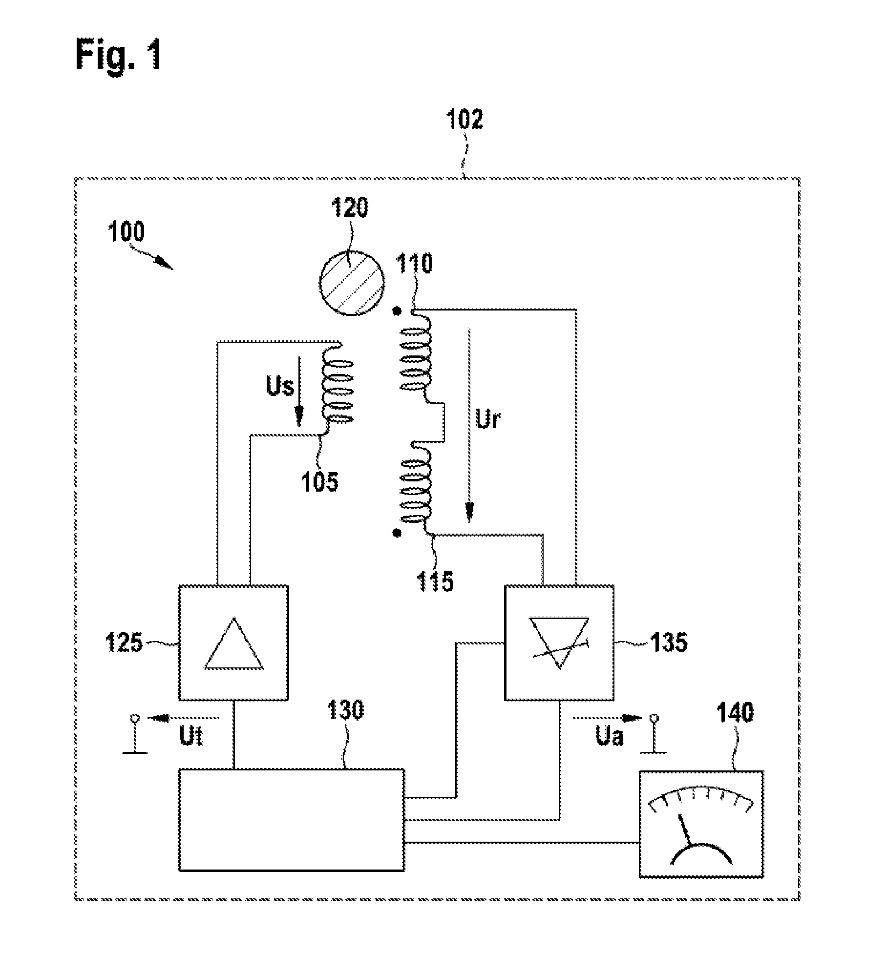
[0026]FIG. 1 shows a measuring apparatus 100 in a metal detector 102. The measuring apparatus 100 comprises a transmission coil 105 which is arranged in the region of a first reception coil 110 and a second reception coil 115. The reception coils 110 and 115 are oriented relative to one another and electrically connected to one another in the region of the magnetic field in such a way that a resulting reception voltage across the reception coils is zero when the magnetic field acts on both reception coils in the same way.

[0027]In particular, the reception coils 110 and 115 are oriented such that longitudinal axes, around which windings of the reception coils 110 and 115 are wound, run parallel to one another. For example, the reception coils 110, 115 can be arranged concentrically to one another or in alignment with one another. Depending on the direction in which the windings of the reception coils 110, 115 are wound around the longitudinal axes, a positive or negative voltage is i...


PUM


Abstract

A measuring apparatus for sensing metal articles, comprises a transmission coil for producing a magnetic field, two reception coils, which are oriented relative to one another, and electrically connected to one another, in the region of the magnetic field such that a resulting received voltage on the reception coils is zero when the magnetic field acts on both reception coils in the same way, a control device configured to supply the transmission coil with an alternating transmission voltage, and a determination device configured to determine the metal article on the basis of the received voltage. In this arrangement, the control device is further configured to control RMS value for the transmission voltage such that the received voltage remains below a predetermined threshold value.

Description

PRIOR ART[0001]Metal detectors which can be used to locate metal articles which can be concealed in walls, in particular, are known. An alternating magnetic field is usually generated by means of a transmission coil in a metal detector of this kind. A pair of reception coils which are connected electrically in series and are oriented back-to-back in parallel is arranged in the region of the generated magnetic field. If there is no metal article in the region of the coils, voltages which are induced in the two reception coils have opposite signs and are cancelled out by the series connection. If a metal article in the magnetic field is at unequal distances from the two reception coils, unequal voltages are induced in the reception coils, with the result that a reception voltage of the reception coils which are connected electrically in series is not equal to zero. The reception voltage is amplified by means of an amplifier and then compared with a threshold value. If the reception vo...

Claims


Application Information

Patent Timeline
Patent Type & Authority Applications(United States)
IPC IPC(8): G01V3/08
CPCG01V3/08G01V3/107
Inventor HAHL, MARKUSWIELAND, CHRISTOPHALBRECHT, ANDREJ
Owner ROBERT BOSCH GMBH
Why Eureka
Try Eureka