Magnetic sensor device
- Summary
- Abstract
- Description
- Claims
- Application Information
AI Technical Summary
Benefits of technology
Problems solved by technology
Method used
Image

Examples
first embodiment
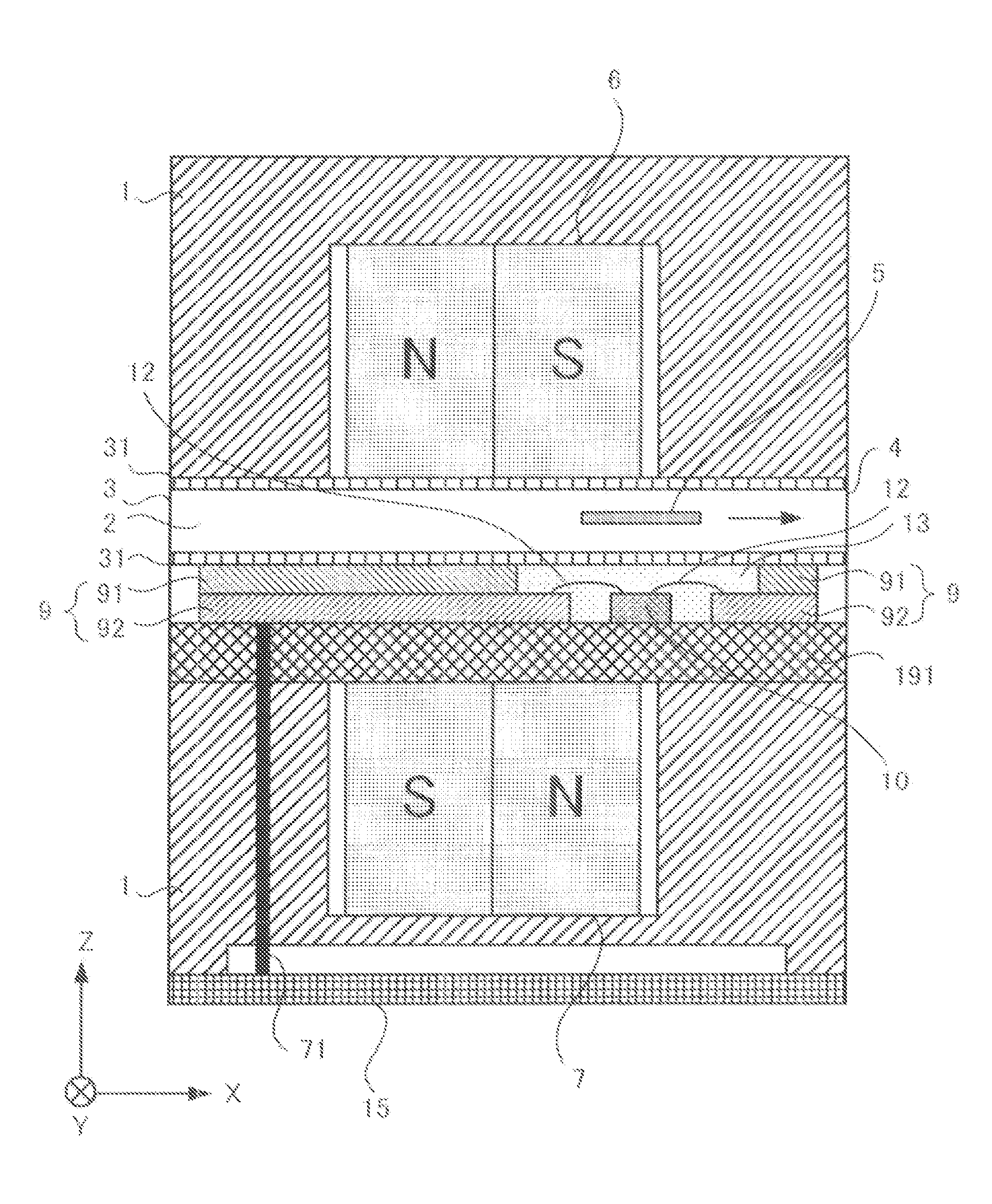
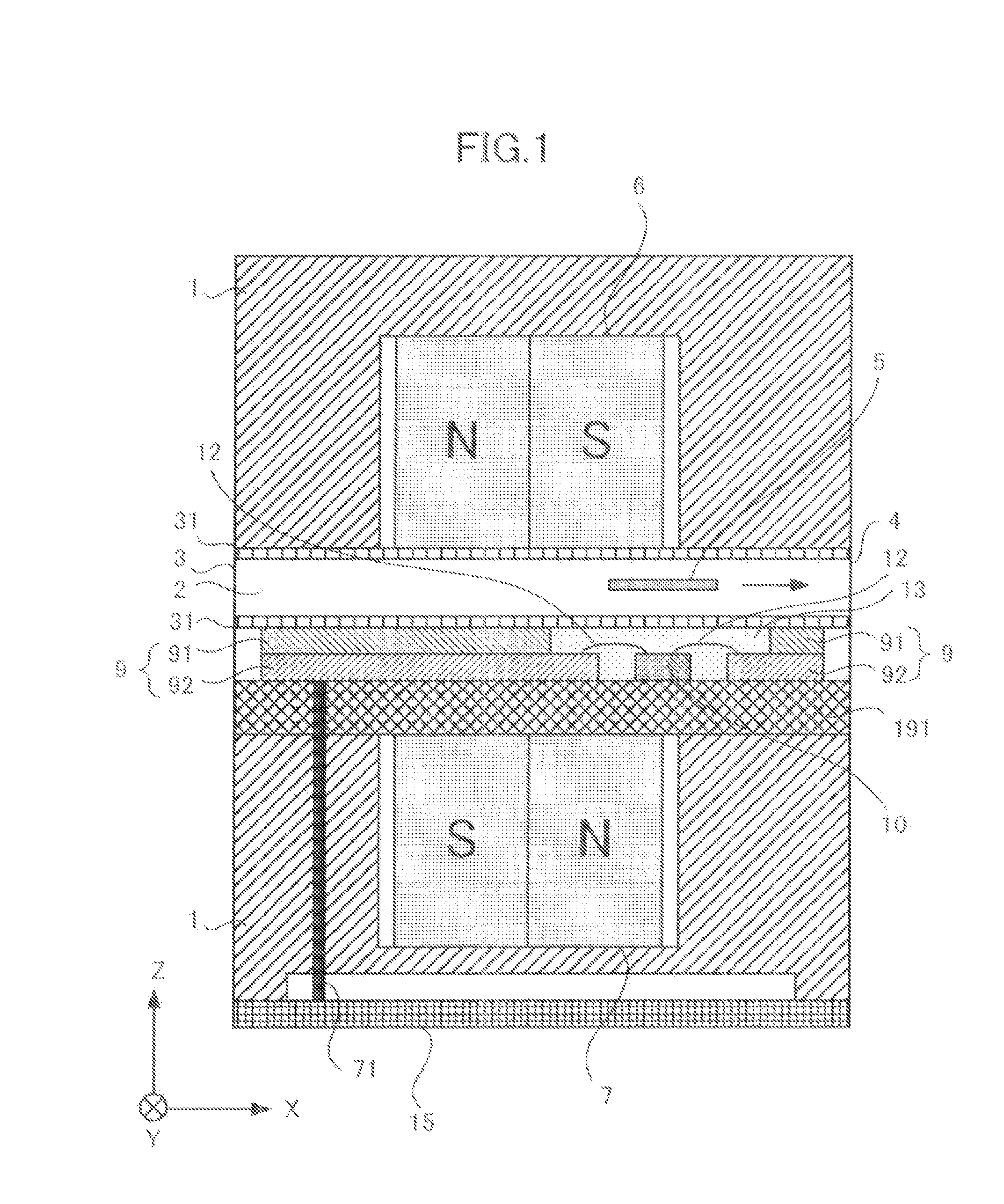
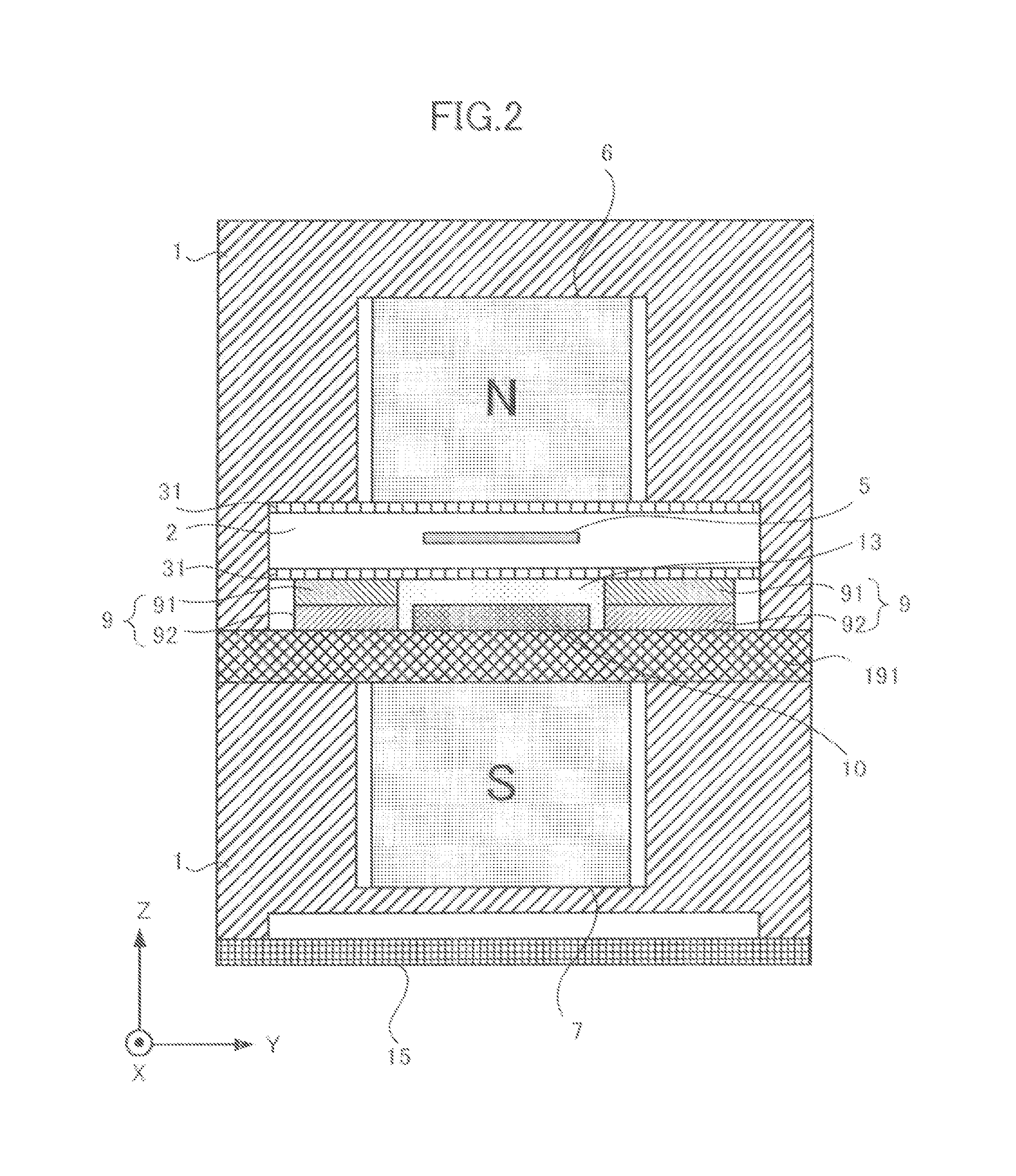
[0047]FIG. 1 is a cross-sectional view along a conveying direction of a magnetic sensor device according to First Embodiment of the present invention. FIG. 2 is a cross-sectional view along a direction orthogonal to the conveying direction of the magnetic sensor device according to the First Embodiment. In drawings, an X axis direction is the conveying direction, a Y axis direction is the reading width direction, and a Z axis direction is the spacing direction. The conveying direction, the reading width direction and the spacing direction are orthogonal to one another. The spacing direction is a direction that vertically passes through the magnetic pattern of an object to be detected 5. A conveyance path 2 is for conveying the object to be detected 5 that is a paper sheet medium such as paper money. The object to be detected 5 is inserted through a first slit 3 formed across the reading width direction on one side (sidewall) of a housing 1. The object to be detected 5 is conveyed in...
second embodiment
[0068]FIG. 12 is a top view of a multilayer board and an AMR element in a magnetic sensor device according to Second Embodiment of the present invention, seen from the conveyance path side. The same components as those in FIG. 4 have the same reference signs. In FIG. 12, the resistor 102a of the AMR element 10 is disposed in such a way that the long side of the rectangular shape of the resistor 102a extends in the reading width direction; the resistor 102b is disposed in such a way that the long side of the rectangular shape of the resistor 102b extends in the conveying direction; a connection point that connects the resistor 102a and the resistor 102b in series is connected to the electrode 101b of the AMR element 10; the other end of the resistor 102a is connected to the electrode 101a; and the other end of the resistor 102b is connected to the electrode 101c.
[0069]FIG. 13 is a diagram illustrating connection of the AMR element and an external circuit in the magnetic sensor devic...
third embodiment
[0072]FIG. 15 is a cross-sectional view along the conveying direction of a magnetic sensor device according to Third Embodiment of the present invention. The same components as those in FIG. 1 have the same reference signs. The magnetic sensor device according to the Third Embodiment further includes: yokes for the first magnet 81 that are a pair of magnetic bodies, each being in contact with each of side surfaces orthogonal to the conveying direction, of side surfaces of the first magnet 6; and the yokes for the second magnet 82 that are a pair of magnetic bodies, each being in contact with each of side surfaces orthogonal to the conveying direction, of side surfaces of the second magnet 7, in addition to the configuration of the magnetic sensor device according to the First Embodiment in FIG. 1.
[0073]FIG. 16 is a diagram illustrating a magnetic field distribution in the spacing direction, the magnetic field distribution being generated by the yokes for the first magnet and the yok...
PUM
 Abstract
Description
Claims
Application Information
 - Generate Ideas
- Intellectual Property
- Life Sciences
- Materials
- Tech Scout
- Unparalleled Data Quality
- Higher Quality Content
- 60% Fewer Hallucinations
Browse by: Latest US Patents, China's latest patents, Technical Efficacy Thesaurus, Application Domain, Technology Topic, Popular Technical Reports.
© 2025 PatSnap. All rights reserved.Legal|Privacy policy|Modern Slavery Act Transparency Statement|Sitemap|About US| Contact US: help@patsnap.com