
Sheet cooling apparatus and image forming apparatus

Inactive Publication Date: 2014-01-30
CANON KK
View PDF9 Cites 9 Cited by
  • Summary
  • Abstract
  • Description
  • Claims
  • Application Information

AI Technical Summary

Benefits of technology

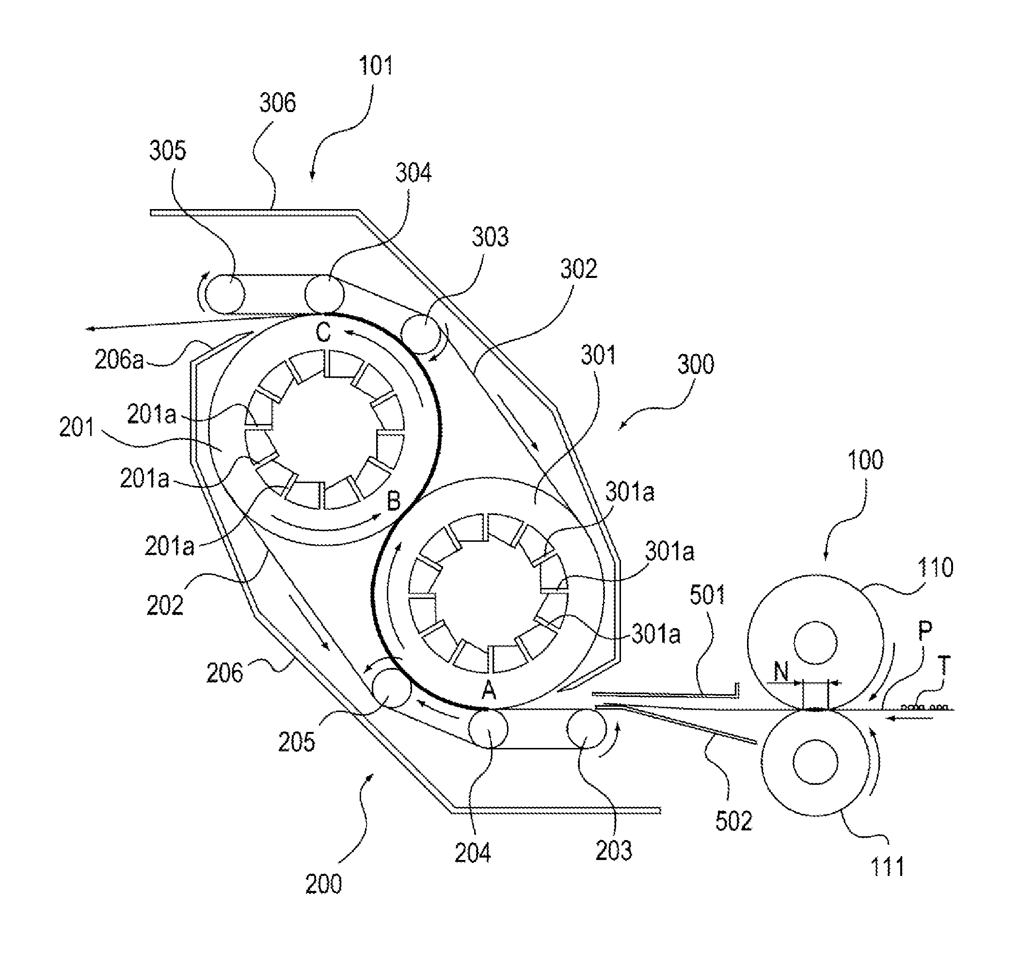
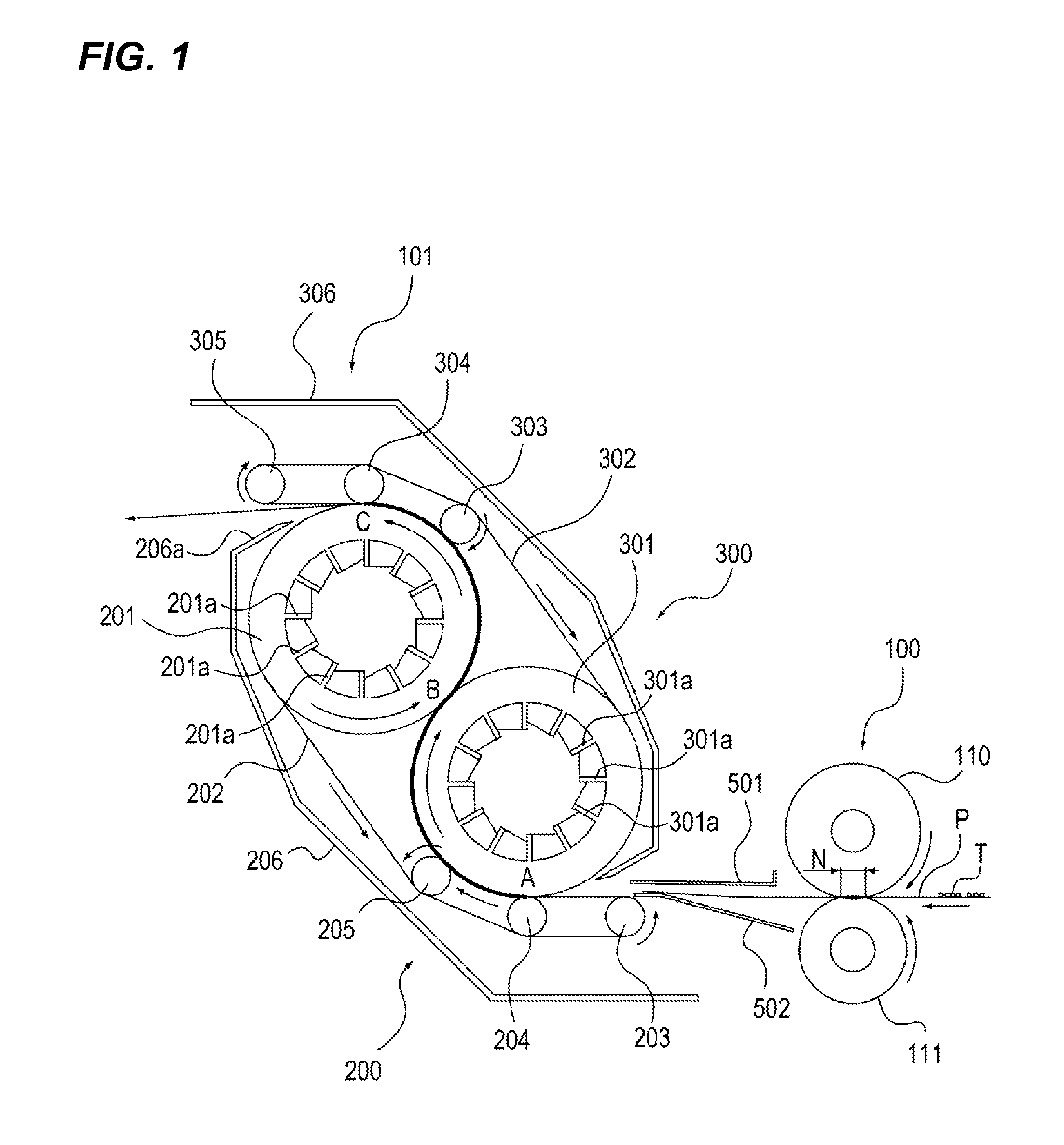
This patent aims to improve the durability and cooling ability of a cooling belt and its members. It introduces a cooling roller that reduces friction with the belt, allowing for stable conveyance of the sheet and reducing driving load. Additionally, the curved conveying path, shaped like a "S," allows for better cooling efficiency and reduces miniaturization of the apparatus. Furthermore, the curved conveying path can also provide a curl correction effect for the sheet.

Problems solved by technology

However, among the above-described conventional technologies, in the technology disclosed in Japanese Patent Laid-Open No. 2009-161347, there is concern that tension of the belt member may increase, and deterioration due to abrasion caused by a contact load of the belt member for the cooling member may become serious.

Method used


Image

  • Sheet cooling apparatus and image forming apparatus
  • Sheet cooling apparatus and image forming apparatus
  • Sheet cooling apparatus and image forming apparatus

Examples


first embodiment

[0040]A sheet cooling apparatus and an image forming apparatus including the sheet cooling apparatus will be described with reference to FIGS. 1 to 12.

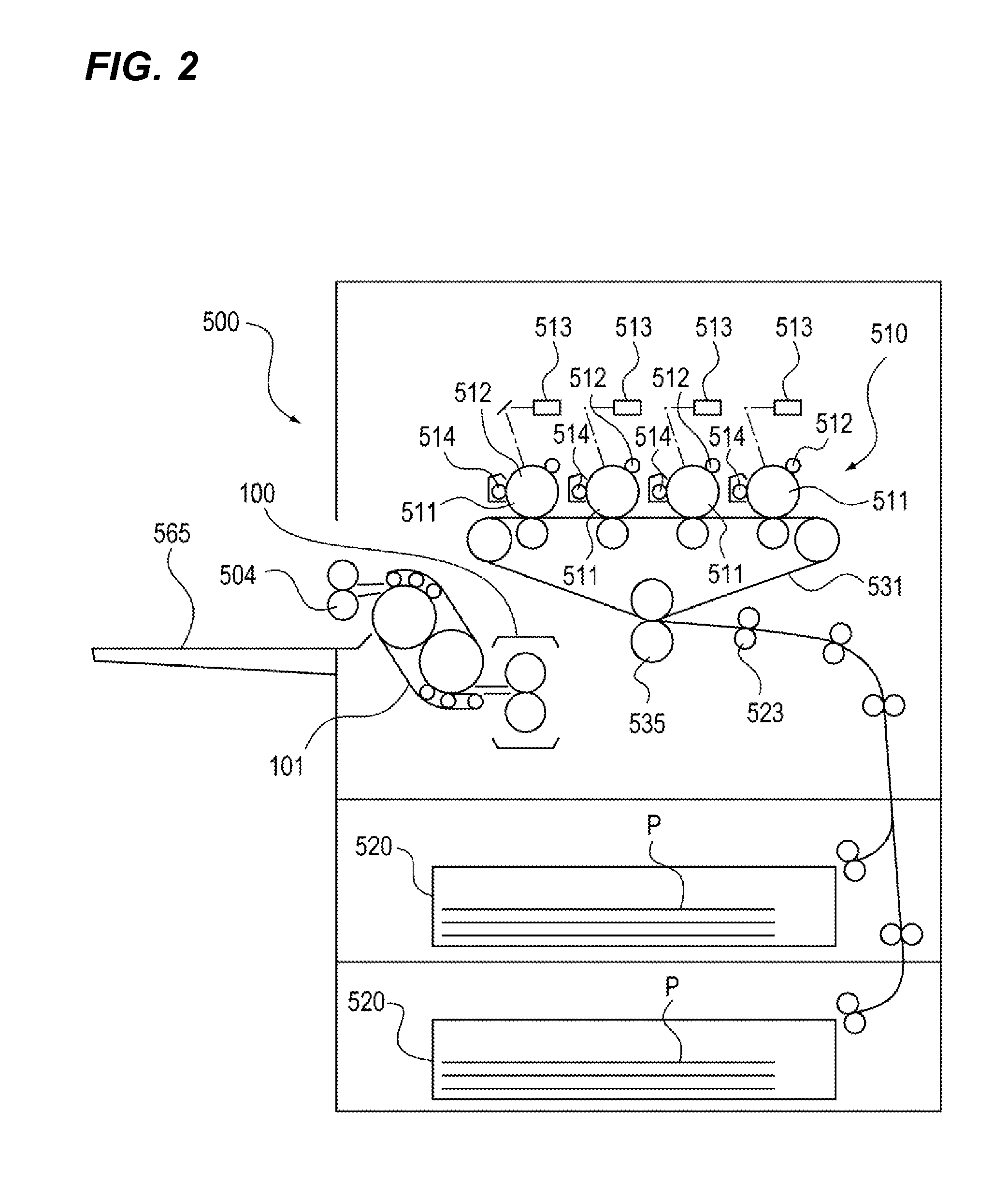
[0041]FIG. 2 is a cross-sectional view of a color electro-photographic printer 500 as an example of the image forming apparatus according to this embodiment and is a cross-sectional view taken along the conveying direction of a sheet. In this embodiment, the color electro-photographic printer will be simply referred to as a “printer”. On a sheet as a recording material, a toner image is formed. As specific examples of the sheet, there are plain paper, a sheet made from a resin that is a substitute for the plain paper, a cardboard, and an overhead projector sheet.

[0042]The printer 500 illustrated in FIG. 2 includes image forming portions 510 of colors Y (yellow), M (magenta), C (cyan), and Bk (black). In the image forming portions 510, toner images of each color to be formed on a sheet are formed. In each image forming portion 510, a p...

second embodiment

[0100]A cooling apparatus 102 as a sheet cooling apparatus will be described with reference to FIGS. 13A to 20. Description of the same portion as that of the above-described first embodiment will not be presented.

[0101]A cooling belt 702 as a second endless belt used for performing frictional conveying while being brought into contact with the rear face of the sheet P, a cooling roller 701, and belt pressure rollers 704 and 705 as second suspension members, and a tension roller 703 configure an independent cooling belt unit 700. The configuration of the cooling belt unit 700 is the same as that of the cooling belt unit 200 according to the above-described first embodiment, and thus, description thereof will not be presented.

[0102]A cooling belt 802 as a first endless belt performs frictional conveyance while being brought into contact with the front surface of the sheet P. This cooling belt 802, as illustrated in FIGS. 13A and 13B, is stretched over the outer circumferences of a co...


PUM


Abstract

There is provided a sheet cooling apparatus that cools a sheet while conveying the sheet passed passing through a fixing device for fixing an unfixed toner image formed on the sheet by heating the toner image, wherein a second suspension member is arranged so as to press a second endless belt on a circumferential face of a first cooling roller through a first endless belt, a first suspension member is arranged so as to press the first endless belt on a circumferential face of a second cooling roller through the second endless belt, and a curved sheet conveying path is formed between the first endless belt and the second endless belt.

Description

BACKGROUND OF THE INVENTION[0001]1. Field of the Invention[0002]The present invention relates to a sheet cooling apparatus used for cooling a sheet, which is formed from paper fibers or the like, that is a target for heating, pressing, and fixing an unfixed toner image in an image forming apparatus such as a copying machine, a printer, or a facsimile machine.[0003]2. Description of the Related Art[0004]Conventionally, in image forming apparatuses such as electro-photographic apparatuses and electrostatic recording apparatuses, an image is formed on a sheet by forming a toner image on the sheet as a recording material and fixing the toner image using a fixing device by heating and pressing the toner image. As fixing devices used in such image forming apparatuses, a roller fixing system is employed in which a pressing nip portion (fixing nip portion) is formed by pressing a pressure roller to a fixing roller having an internal heater and performing fixing by performing heating and pre...

Claims


Application Information

Patent Timeline
IPC IPC(8): G03G15/20
CPCG03G15/2039G03G15/2021G03G15/6573G03G21/206G03G2215/00662G03G2221/1645
Inventor OKUDA, KAZUHISA
Owner CANON KK
Learn More