Active clearance control manifold system

a technology of active clearance control and manifold, which is applied in the direction of engines, mechanical equipment, machines/engines, etc., can solve the problems of affecting engine performance, specific fuel consumption, and/or exhaust gas temperature margin, adversely affecting thrust, specific fuel consumption, and/or specific fuel consumption

Active Publication Date: 2014-01-30
GENERAL ELECTRIC CO
View PDF4 Cites 69 Cited by
  • Summary
  • Abstract
  • Description
  • Claims
  • Application Information

AI Technical Summary

Problems solved by technology

For example, excessive blade tip clearances may adversely affect thrust, specific fuel consumption, and / or exhaust gas temperature margin.
The problems: Some active clearance control systems may be ineffective at controlling blade tip clearances due to limited heat transfer capacity and / or some active clearance control systems may adversely affect engine performance due to their use of relatively large amounts of thermal control air.

Method used


Image

  • Active clearance control manifold system
  • Active clearance control manifold system
  • Active clearance control manifold system

Examples


Embodiment Construction

[0018]In the following detailed description, reference is made to the accompanying drawings, which form a part hereof. In the drawings, similar symbols typically identify similar components, unless context dictates otherwise. The illustrative embodiments described in the detailed description, drawings, and claims are not meant to be limiting. Other embodiments may be utilized, and other changes may be made, without departing from the spirit or scope of the subject matter presented here. It will be readily understood that the aspects of the present disclosure, as generally described herein, and illustrated in the figures, can be arranged, substituted, combined, and designed in a wide variety of different configurations, all of which are explicitly contemplated and make part of this disclosure.

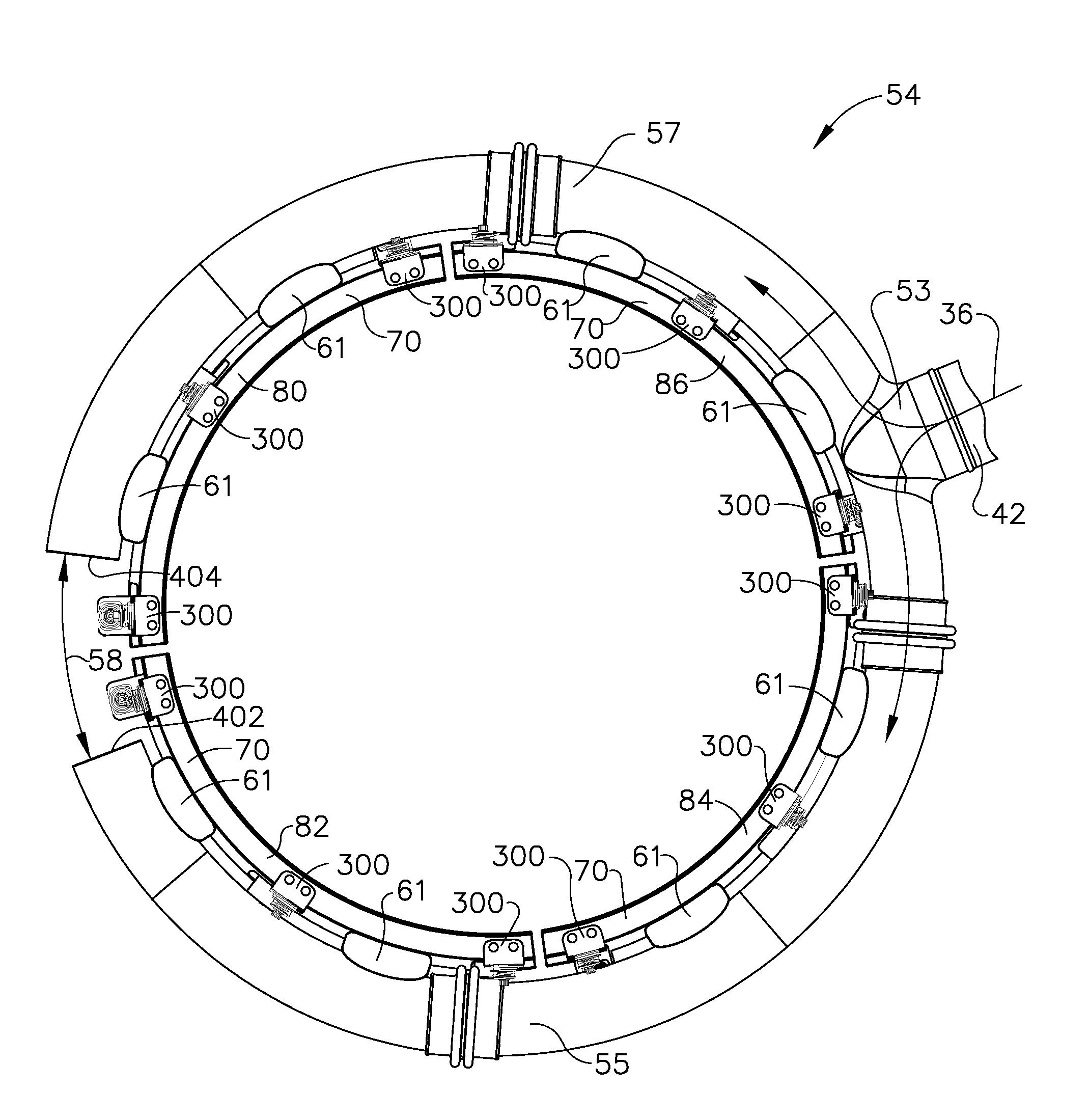
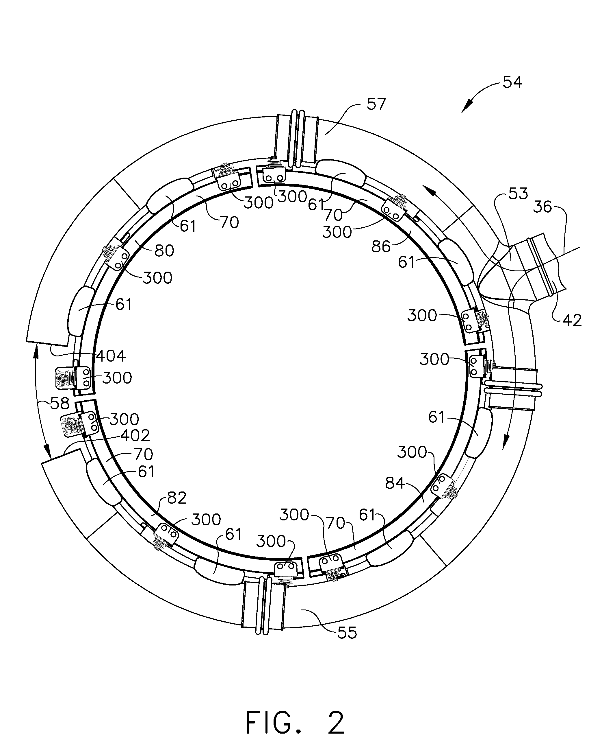
[0019]The present disclosure includes, inter alia, gas turbine engines, and, more specifically, active clearance control systems for gas turbine engines.

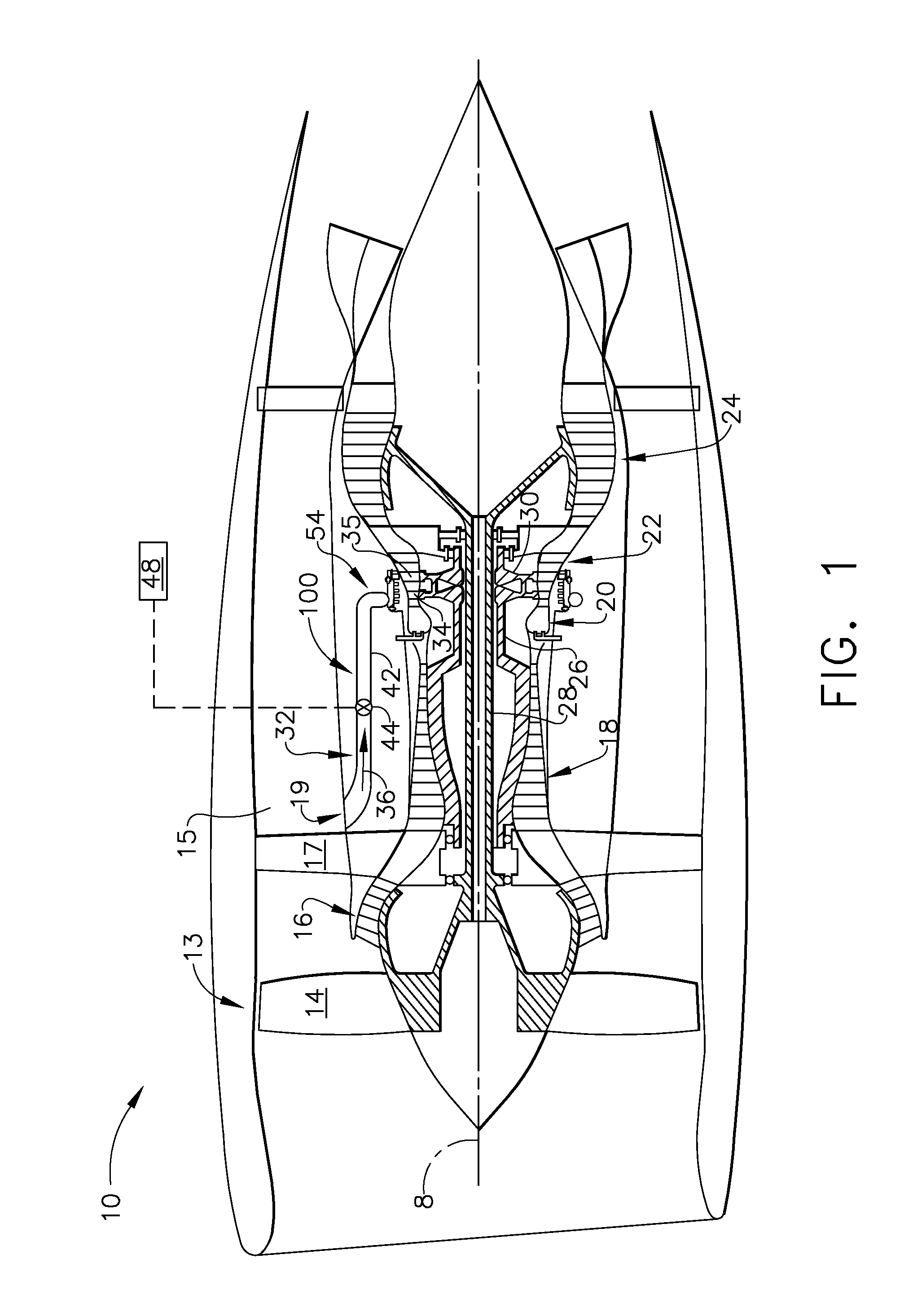
[0020]FIG. 1 is a schematic cross section...


PUM


Abstract

Active clearance control systems for gas turbine engines are disclosed. An example active clearance control system may include a generally circumferentially mounted spray tube comprising a plurality of impingement holes arranged to impinge thermal control air on a clearance control component of a case; a rigid mounting assembly substantially rigidly coupling the spray tube to the case; and / or a sliding mounting assembly coupling the spray tube to the case while permitting limited relative movement between the spray tube and the case in a direction generally parallel with an engine axis. The sliding mount may be coupled to the case generally axially forward of the rigid mount. A ratio of the stand-off distance to the impingement hole diameter may be less than about 8. A ratio of the arc spacing to the impingement hole diameter may be less than about 15.

Description

CROSS REFERENCE TO RELATED APPLICATION[0001]This application claims the benefit of U.S. Provisional Application No. 61 / 675,396, filed Jul. 25, 2012, which is incorporated by reference herein in its entirety.BACKGROUND[0002]The subject matter disclosed herein relates generally to gas turbine engines, and, more specifically, to active clearance control systems for gas turbine engines.[0003]In some gas turbine engines, such as those used to propel aircraft, some aspects of engine performance may depend upon clearances between turbine blade tips and static seals or shrouds surrounding the blade tips. For example, excessive blade tip clearances may adversely affect thrust, specific fuel consumption, and / or exhaust gas temperature margin.[0004]Some gas turbine engines may use active clearance control to adjust turbine blade tip clearances at various engine operating conditions. For example, some active clearance control systems may be configured to direct relatively cool or relatively hot...

Claims


Application Information

Patent Timeline
Patent Type & Authority Applications(United States)
IPC IPC(8): F01D11/24
CPCF01D11/24F05D2200/33F05D2260/201Y02T50/60F01D25/12F01D25/14F05D2260/30
Inventor SCHIMMELS, SCOTT ALANFUSINATO, DANIEL JOHNGLESSNER, JOHN CARLMIRKOVICH, DAN NICHOLASPROCTOR, ROBERT
Owner GENERAL ELECTRIC CO
Why Eureka
Try Eureka